Mazda MAZDA5 2006 Скачать руководство пользователя страница 6

6

1030658 Rev.A 09/05

REMOTE START CONTROL MODULE PREPARATION

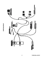
1. Insert the supplied fuses into the remote start control module as shown in below (FIGURE Z).

the fuses fit tight so use a tool handle to seat them in place if necessary.

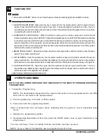
2. Install DNA card into the remote start control module as shown below. (FIGURE AA)
   NOTE:  Use care to assure that both rows of the multipin connectors are aligned and seated properly.

3. Plug the supplied wire harness 10-way and 24-way connectors into the remote start control mod-

ule (FIGURE BB). Make sure the harnesses are seated completely.  NOTE:  The connectors will
only  plug into the remote start control module one way.

4. Plug the supplied immobilizer interface 4-way connector into the remote start control module.

(FIGURE BB)

NOTE: TAPE OFF THE WHITE WIRE (IF EQUIPPED) COMING FROM THE 4-WAY
CONNECTOR (THIS WIRE IS NOT USED ON THIS SYSTEM).

4

FIGURE Z

5

15

15

15

15

15

15

5

15

15

15

15

15

15

-+

-+

15

HVAC 1

HVAC 2

MAIN B+

IGNITION

DOME LIGHT

PK LIGHTS

DOOR LOCKS

15

TRUNK RELEASE

To Immobilizer
Interface Module

FIGURE BB

FIGURE AA

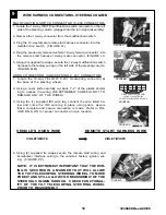
REMOTE ENGINE START MODULE AND IMMOBILIZER INTERFACE MOUNTING

5

REMOTE ENGINE START MODULE MOUNTING
1. Route the dipole antenna cable  (previously installed in step 2)

and plug into the 2-pin connector on the bottom of the remote
start control module.

2. Locate the large dashboard support bracket to the left of the

steering column.

3. Using (3) supplied long tie wraps secure the remote start con-

trol module to the left side of the dashboard support bracket.
Make sure that the remote start control module is not mounted
to far down on the bracket, this will eliminate problems with
dashboard reassembly.  (FIGURE CC)

IMMOBILIZER INTERFACE MODULE MOUNTING
1. Locate the Large dashboard support bracket to the left of the

steering column.

2. Using (1) supplied long tie wrap, secure the immobilizer inter-

face to the dashboard bracket.  (FIGURE DD)

Tie Wraps

FIGURE CC

Tie Wraps

FIGURE DD

Содержание MAZDA5 2006

Страница 1: ...v hicule est dot d un d marreur distance Pour r duire les risques de blessures graves ou mortelles mettre le d marreur distance en mode service et d brancher la batterie du v hicule avant d effectuer...

Страница 2: ...hillips screw behind each panel FIGURE E f Remove the automatic shifter knob by carefully unscrew ing the shifter knob FIGURE F g Using a fiber stick remove the automatic shifter bezel on the center c...

Страница 3: ...Slide the removed white clip into position on the A pillar panel FIGURE L 2 Clean mounting spot with an alcohol pad prior to mounting Mount the dipole antenna to the windshield 210mm to the right of...

Страница 4: ...ie wraps FIGURE O Q 3 Route the hood safety switch wiring along the cowl panel tucking under the cowl panel where possible into the engine compartment towards the hood release cable grommet FIGURE O R...

Страница 5: ...h wire to harness as shown FIGURE W d Pull fish wire and wiring through hood release cable opening FIGURE O page 4 e Tape the hood safety switch wires against the fish wire and electrical tape in plac...

Страница 6: ...SYSTEM 4 FIGURE Z 5 15 15 15 15 15 15 5 15 15 15 15 15 15 15 HVAC 1 HVAC 2 MAIN B IGNITION DOME LIGHT PK LIGHTS DOOR LOCKS 15 TRUNK RELEASE To Immobilizer Interface Module FIGURE BB FIGUREAA REMOTE EN...

Страница 7: ...CH MOUNTING WIRE CONNECTIONS 1 Locate the BLACK ORANGE and GRAY RED wire from the remote start system harness 2 Locate the wires listed below If the hood safety switch wire has a ground ringlet termin...

Страница 8: ...8 1030658 Rev A 09 05 SYSTEM LAYOUT...

Страница 9: ...cing the ignition key opening FIGURE HH II 5 Using a supplied tie wrap secure the antenna coil FIGURE HH II FIGUREGG FIGUREHH FIGUREII WIRE HARNESS CONNECTIONS STEERING COLUMN 9 IGNITION SWITCH CONNEC...

Страница 10: ...steering wheell 2 Using a razor knife carefully cut back 1 2 of the plastic shield ing to expose the wiring BE EXTREMELY CAREFUL NOT TO DAMAGE ANY OF THE WIRES 3 Using the 1 supplied IDC wire tap con...

Страница 11: ...of the IDC wire tap and crimp in place with pliers 10 REMOTE START HARNESS VEHICLE WIRE GREEN YELLOW GREEN YELLOW FIGUREQQ EMERGENCY OVERRIDE PROGRAMMING BUTTON MOUNTING 1 Locate the previously remov...

Страница 12: ...rd panel and re secure the weather seal c Secure the center console panel and re install the 3 phillips screws around the shifter assembly and 1 phillips screw on each side of the lower center console...

Страница 13: ...he brake pedal to shut down the remote starter system b Using the first key turn the ignition on wait for the THEFT light to turn off then turn the ignition off and remove key from the ignition switch...

Страница 14: ...ake pedal The vehicle should shut off 4 KEY IN SENSE Insert the ignition key into the ignition switch but keep in off position activate the remote engine start function the vehicle should flash the li...

Страница 15: ...will need to be adjusted to shutdown the vehicle when the hood is raised to the full upright position 1 Raise and prop the vehicle s hood 2 The hood switch cylinder should be bend away from the hood...

Страница 16: ...DOOR UNLOCK OUTPUT PROGRAMMING OVERIDE BUTTON PROGRAMMING OVERIDE BUTTON DRVR S UNLOCK OUTPUT TRUNK OUT DRVR S UNLOCK OUTPUT TRUNK OUT PROGRAMMING OVERIDE BUTTON PROGRAMMING OVERIDE BUTTON HOOD OPEN S...

Страница 17: ...E ATTENTION Installation Instruction change for P N 0000 8F L05B The Fuse placement position changed for REMOTE START SYSTEMS on all Mazda 5 vehicles The Dome Light Fuse must be placed in the positive...

Страница 18: ...e side of Ignition Coil in pin 2BE 2006 2007 models or pin 2G 2008 models of the 60 pin front connector at the PCM Refer to FIGURE A B for proper connector and pin location 4 Using a razor knife caref...

Страница 19: ...ing option 2 g Press and release the brake pedal The horn will beep 3 times indicating option 3 h Press the START button on the transmitter one time i Press and release the programming button a third...

Страница 20: ...ns b Ensure brake pedal is not depressed c Ensure good connection and correct vehicle brake wire See Step 10 of Installation Instructions d Disengage Service Valet Mode See Page 4 of Owner s Manual 5...

Отзывы: