


11
1030658 Rev.A 09/05
WIRE HARNESS CONNECTIONS- BRAKE SAFETY
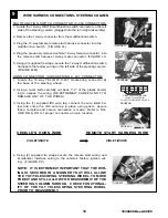
1. Locate the wire harness running along the firewall on the left side
of the steering column near the hood release cable (directly in
front of the module mounting location). (FIGURE QQ)
2. Locate the wire GREEN/YELLOW brake switch wire. NOTE: There
will be only (1) GREEN/YELLOW wire in this harness.
3. Place (1) supplied IDC wire tap on to the vehicle wire (using the
side of the IDC wire tap that is open on both ends).
4. Insert the wire from the remote start harness into the other side of
the IDC wire tap and crimp in place with pliers.
10
REMOTE START HARNESS
VEHICLE WIRE
GREEN/YELLOW
GREEN/YELLOW
FIGURE QQ
EMERGENCY OVERRIDE/PROGRAMMING BUTTON MOUNTING
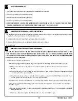
1. Locate the previously removed driver’s side kick panel cover.
2. Drill a 9/32” hole at the top of the panel, approximately 76mm down and 102mm from the far edge.
3. Route the emergency override/programming button from the remote start harness down to the kick
panel.
4. Mount the emergency override/programming button in the drilled hole from behind and screw the mounting
cap in place. (FIGURE RR)
NOTE: DISCARD THE LOCK WASHER FROM THE EMERGENCY OVERRIDE/PROGRAM-
MING BUTTON, IT IS NOT USED ON THIS MODEL.
5. Re-install driver’s side kick panel cover
11
FIGURE RR
76mm
102mm
Содержание MAZDA5 2006
Страница 8: ...8 1030658 Rev A 09 05 SYSTEM LAYOUT...