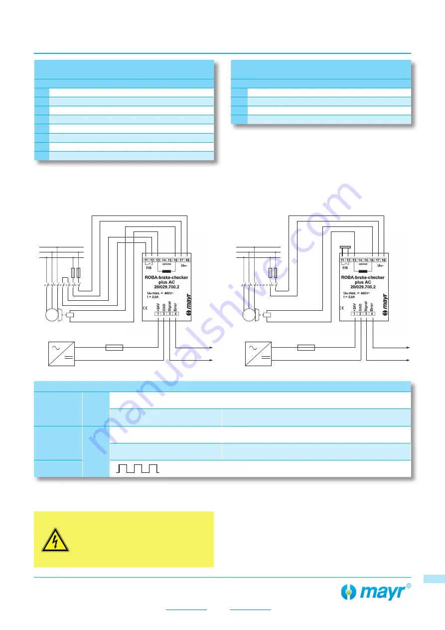
+
-
24 VDC
L1
L2
L3
M
3 ~
+
-
24 VDC
L1
L2
L3
M
3 ~
Installation and Operational Instructions for
ROBA
®
-brake-checker plus AC Type 029.700.2
(B.0297002.EN)
your reliable partner
26/06/2019 HH/GF
Page 5 of 10
Chr. Mayr GmbH + Co. KG
Eichenstraße 1, D-87665 Mauerstetten, Germany
Tel.: +49 8341 804-0, Fax: +49 8341 804-421
www.mayr.com
, E-Mail:
55
Electrical connection
Control terminal
1 Input v24 VDC
2 Input voltage 0 VDC
3 Signal (output) max. 100 mA
4 Error (output) max. 100 mA
Electrical connection
Power terminal
11 F/S (see wiring examples)
12 F/S (see wiring examples)
13 Output voltage -
14
Do not assign!
15
Do not assign!
16 Output v
17 Supply voltage VAC
18 Supply voltage VAC
Outputs
Signal
3
0 VDC (low)
Brake is not energised, movement of the armature disk for
closing the brake.
24 VDC (high)
2)
Brake energised, movement of the armature disk for opening
the brake.
Error
4
24 VDC (high)
2)
no errors
0 VDC (low)
Brake does not open or close, line interruption, false detec-
tion
Warning
1)
Preventative function monitoring (wear recognition and error
recognition, functional reserve)
1) Rectangular signal 10 Hz / 24 Vpp
2) Voltage corresponds to input voltage of control terminal
DANGER
Danger of death! Do not touch voltage-
carrying lines and components.
No mains separation!
Voltage control through phase angle control
system
Wiring Example
(400 VAC,
DC-side, fast switching)
Wiring Example
(400 VAC,
AC-side, slow switching)
55


