CALIBRATE TENSION THROUGH FIELDBUS
www.maxcessintl.com
DLCA NET-S1
MI 850A374 1 A
Page 55 of 67
9.1
Precision calibration procedure
To get full 14-bit resolution, you must use three significant digits
when entering calibration weight. See the chart for entering
Maximum Tension in Section 8.2.
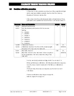
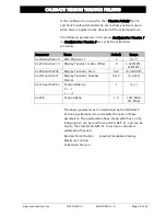
Enter values into the calibration parameters shown below. These
parameters are available for Tension Zone 1 and Tension Zone 2.
Parameter Name and description
Default
Range
0x207
0x217
Decimal Point Position
Sets the decimal point position for the tension
display.
0 = 000000
1 = 000000.
2 = 00000.0
3 = 0000.00
4 = 000.000
5 = 00.0000
6 = 0.00000
0
{0, 6}
0x20D
0x21A
Calibration Tension
Calibration tension is the force of the known weight
hanging on the rope over the load cells.
500
{0,
999000}
0x211
0x21E
Maximum Tension
Maximum tension is the maximum tension expected
for the application. Do not exceed the rating of the
load cells.
500
{0,
999000}
Set the Load Cell excitation voltage 0x201. See section 7.3.
When performing a calibration, the following calibration sequence
must be done in order listed and in full before a calibration is
valid.
If only zeroing the tension is required, use the 0x1E or 0x1F
command.
Precision calibration steps begin on page 56.
Refer to Figure 8 on page 54.

