21
20
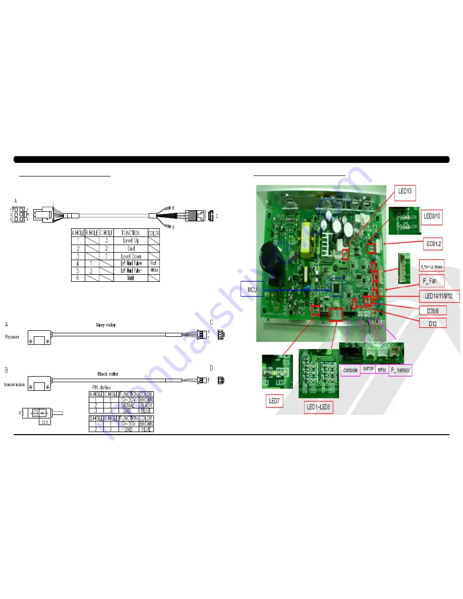
8.1 ElECTRICAl dIAgRAMS - CoNTINUEd
CHAPTER 8: TRoUblESHooTINg
g18 - H/P CoNNECT wIRE
P51 - IR SENSoR wIRE
8.2 lCb ERRoR INdICAToRS
Страница 1: ...C 5 x 0 5 C l i m b M i l l S E R V I C E M A N U A l...
Страница 2: ...3 Troubleshooting No Power to the Console 33 8 14 Troubleshooting Heart Rate Issues 34 8 15 Troubleshooting Toggle Issues 37 CHAPTER 9 PART REPLACEMENT GUIDE 9 1 Side Cover Replacement 40 9 2 Console...
Страница 3: ...1 1 1 SERIAL NUMBER LOCATION Chapter 1 Serial Number Location SERIAL Number LOCATION...
Страница 4: ...are being used or when oxygen is being administered Do not use the equipment in any way other than designed or intended by the manufacturer It is imperative that all Matrix Fitness Systems equipment i...
Страница 5: ...at all times and is recommended when add on accessories are used For units with an integrated TV like the 7xe and 7xi the TV power requirements are included in the unit An RG6 coaxial cable with F Ty...
Страница 6: ...ilar to an emergency stop on a treadmill 5 Unplug the Climbmill and clean the AUTO STOP SENSORS located under the bottom step Control Zone sensor with a cotton swab and rubbing alcohol Chapter 3 Preve...
Страница 7: ...POLAR telemetric strap or continually hold onto the contact heart rate grips for this workout Locate the metal sensors on the handlebars of the Climb Mill Notice that there are two separate pieces of...
Страница 8: ...elected during program set up Default User Weight 150 lbs 68 kg 80 lbs 36 kg 400 lbs 182 kg Weight used for program calorie expenditure calculations Accumulated Floors N A 0 999 999 Miles Total floors...
Страница 9: ...into sleep mode E Stop Switch On Off or On This option selects the E Stop function E Stop Setting 100 4 500 Adjusts the touched point of the E Stop Audio Source Off Off TV PCTV Remote TV a Off no TV k...
Страница 10: ...15 14 8 1 electrical diagramS Chapter 8 Troubleshooting 8 1 electrical diagramS CONTINUED Chapter 8 Troubleshooting...
Страница 11: ...P01 DIGITAL COMMUNICATION WIRE P13 Speed Sensor Extension Wire 8 1 electrical diagramS CONTINUED Chapter 8 Troubleshooting 8 1 electrical diagramS CONTINUED Chapter 8 Troubleshooting P27 HAND PULSE W...
Страница 12: ...PROXIMITY SENSOR WIRE 8 1 electrical diagramS CONTINUED Chapter 8 Troubleshooting P04 ECB LOAD WIRE 8 1 electrical diagramS CONTINUED Chapter 8 Troubleshooting P19 POWER SENSOR WIRE P18 CONTROL ZONE S...
Страница 13: ...21 20 8 1 electrical diagramS CONTINUED Chapter 8 Troubleshooting G18 H P CONNECT WIRE P51 IR SENSOR WIRE 8 2 LCB ERROR INDICATORS Chapter 8 Troubleshooting...
Страница 14: ...p of ECB1 and ECB2 There should be a gap of 5mm between the ECB and the flywheel Adjust the gap as shown in Section 9 16 FIGURE A led status Description LED1 LCB status blinking OK LED2 Start or Stop...
Страница 15: ...ance is out of the range replace the ECB If the ECB resistance is within the range replace the LCB b Check the gap of ECB1 and ECB2 Figure B There should be a gap of 5mm between the ECB and the flywhe...
Страница 16: ...sec 2 SOLUTION a Check the power extend wire connection between the brake and LCB for any damage Figures A B b Check to see if the stairs will move when you are in the stop position If yes replace th...
Страница 17: ...b Once power on the control zone 3 IR sensors are no power or hidden over 3 seconds c After power on the control zone 3 IR sensors are no power or hidden over 4 hours 2 SOLUTION a Check if there s so...
Страница 18: ...or 1 SYMPTOM a The frame IR sensors are no communication or disconnected over 3 seconds b Once power on the frame IR sensors are no power or hidden over 3 seconds c After power on the frame IR sensors...
Страница 19: ...eck the fitness room power If LED 15 is still not lit after verifying the fitness room power replace the power cord b Check to see if LED D15 is lit on the LCB Figure A If LED D15 is not lit check for...
Страница 20: ...ate Issues Continued Remove the 2 screws going into the handlebar connection frame from the bottom Figure E Remove the 3 screws going into the handlebar connection frame from the top Figure F Pull the...
Страница 21: ...ohms place one prong of your multi meter on the ground wire coming from the HR board Figure N and the other on the console ground wire that comes out of the console and plugs into the ground wire goi...
Страница 22: ...there is not a reading replace this section of the grip wiring Repeat the previous step with the opposite side grip wiring Figure J figure F figure E figure J figure I figure H figure G 8 15 TROUBLES...
Страница 23: ...the 3 screws and remove the small Matrix logo cover at the top of the stairs Figures C D figure a figure b figure c figure d Chapter 9 Part Replacement guide 9 1 SIDE COVER REPLACEMENT CONTINUED 5 Rot...
Страница 24: ...b Mill for function as outlined in Section 9 21 figure B figure A Chapter 9 Part Replacement guide Chapter 9 Part Replacement guide 9 3 OVERLAY KEYPAD REPLACEMENT NOTE The instructions below are for c...
Страница 25: ...astic Figure J 12 Use the same procedure to replace any additional faulty overlays NOTE Overlays can not be reused 13 Test the Climb Mill for function as outlined in Section 9 21 figure h figure i fig...
Страница 26: ...erse Steps 1 13 to install a new front shroud 15 Test the Climb Mill for function as outlined in Section 9 21 figure E figure F figure H figure G figure J figure I Chapter 9 Part Replacement guide 9 5...
Страница 27: ...andlebar and hand grip cable Figure D figure D figure C Chapter 9 Part Replacement guide 9 6 UPPER HANDLEBAR REPLACEMENT SET CONTINUED 6 Disconnect the wire that connects the left hand grip cable to t...
Страница 28: ...to install a new lower handlebar set 6 Test the Climb Mill for function as outlined in Section 9 21 figure a figure b 9 8 HANDLEBAR SERVICE Chapter 9 Part Replacement guide 1 Turn off the power and di...
Страница 29: ...equence is X shaped clip bearing washer chain spacer stair 2 Do not reuse the X washer retainers Order replacements with your stair or bearing order figure a figure b figure c figure D 9 9 STAIR REPLA...
Страница 30: ...he drive set Figure D These include 2 fan wires 2 ECB wires and a brake wire 7 Loosen the drive set guide screw if tight Figure E 8 Remove the 4 screws that hold the drive set to the frame Figure F fi...
Страница 31: ...torqued to 60 N m 6 Rotate the chain until a spring clip is in a convenient location and remove it Figure C NOTE This chain link will normally be painted to make it easier to identify 7 Remove the jo...
Страница 32: ...function as outlined in Section 9 21 figure a figure C figure D Chapter 9 Part Replacement guide figure B 9 13 FAN REPLACEMENT Chapter 9 Part Replacement guide figure a figure b figure D figure C 1 T...
Страница 33: ...tallation rotate the belt at least 3 full revolutions to insure the belt is centered 8 Reverse Steps 1 5 to re assemble the unit 9 Test the Climb Mill for function as outlined in Section 9 21 figure B...
Страница 34: ...nd re assemble the unit 13 Test the Climb Mill for function as outlined in Section 9 21 figure E figure F figure G 9 16 ECB replacement 1 Turn off power and disconnect the cord from the machine 2 Foll...
Страница 35: ...ensor NOTE Install the speed sensor so that the encoder has a distance of 1 5mm from the optic disk on each side Figures D E 7 Test the Climb Mill for function as outlined in Section 9 21 figure a fig...
Страница 36: ...e stairs at least 2 complete revolutions to make sure the sensor does not hit NOTE The sensor has a signal LED located near the mounting screws The sensor should be mounted close enough to trigger thi...
Страница 37: ...or tests 12 Test the Climb Mill for function as outlined in Section 9 21 figure e figure f figure G figure H 9 21 TESTING THE CLIMB MILL Once the unit or replacement part is fully installed and assemb...
Страница 38: ...heart rate fitness test Sub Maximal Test CPAT WFI Test constant watts CSAFE READY FITLINXX CERTIFIED Yes NETPULSE COMPATIBLE Yes Fit Touch Technology No On the fly program change Yes Integrated Vista...
Страница 39: ...ued step 2 Blue Green HARDWARE BAGS CHAPTER 10 CLIMB MILL specifications and assembly guide 1 Open the Blue and Green hardware bags 2 Attach the Lower Handlebar using the provided bolts Tighten secure...
Страница 40: ...ed 3 Attach the console to the console mast using the screws removed from the console earlier Secure tightly being careful not to pinch any wires 10 3 Climb Mill assembly steps continued step 4 Base S...
Страница 41: ...y guide 10 5 MYE TV BRAcket installation instructions Chapter 10 Climb Mill Specifications and assembly Guide The Matrix Climb Mill is capable of having a MYE Entertainment or Web Ready PCTV televisio...
Страница 42: ...s Continued 13 Press the entertainment keypad overlay into the cutout in the console plastic Figure M 14 Plug the ribbon cable into the open pins on the UCB Figure N Make sure that the pins and ribbon...
Страница 43: ...uctions Continued Figure Q Figure R Figure S Figure T Figure U Figure V 25 Plug the controller wire into the TV Figure W 26 Plug the TV power wire coming from the console mast into the 4 pin black con...
Страница 44: ...ntertainment or Web Ready PCTV television installed using an integrated bracket Follow the instructions below to install the PCTV and TV bracket and the instructions located in the PCTV owner s manual...
Страница 45: ...bracket kit Figure L NOTE Make sure that the slot in the rabbit ear lines up with the spring pin installed in Step 11 to limit the angle of the TV Figure G Figure H Figure I Figure J Figure K Figure L...
Страница 46: ...d marked TO CONSOLE into the TV controller extension wire that should be sticking out the bottom of the console from Step 9 Figure X Figure S Figure T Figure U Figure V Figure W Figure X 10 6 PCTV BRA...
Страница 47: ...and the display will go back to standard operation Chapter 11 software upgrade procedure 11 2 software upgrade procedure FOR LCB figure b figure a NOTE The instructions below are LCB 1 software upgrad...
Страница 48: ...91 90 notes MATrix Fitness systems corp 1610 Landmark Drive Cottage Grove wi 53527 USA TOLL FREE 866 693 4863 www matrixfitness com FAX 608 839 1717 REV 01 KO...