background image

Contents

Dimensions

. . . . . . . . . . . . . . . . . . . . . . . . . . . . . . . . . . . . . . . . . . . . . . . . . . . . . . . . . . . . . . . . . . . . . . . . 2

Safety Information

. . . . . . . . . . . . . . . . . . . . . . . . . . . . . . . . . . . . . . . . . . . . . . . . . . . . . . . . . . . . . . . . . . 3

Product overview

. . . . . . . . . . . . . . . . . . . . . . . . . . . . . . . . . . . . . . . . . . . . . . . . . . . . . . . . . . . . . . . . . . . 6

Introduction

. . . . . . . . . . . . . . . . . . . . . . . . . . . . . . . . . . . . . . . . . . . . . . . . . . . . . . . . . . . . . . . . . . . . . . . . 7

Unpacking . . . . . . . . . . . . . . . . . . . . . . . . . . . . . . . . . . . . . . . . . . . . . . . . . . . . . . . . . . . . . . . . . . . . . . . . 7
Using for the first time . . . . . . . . . . . . . . . . . . . . . . . . . . . . . . . . . . . . . . . . . . . . . . . . . . . . . . . . . . . . . . . 7

Physical installation

 . . . . . . . . . . . . . . . . . . . . . . . . . . . . . . . . . . . . . . . . . . . . . . . . . . . . . . . . . . . . . . . . 8

Adjustable mounting bracket . . . . . . . . . . . . . . . . . . . . . . . . . . . . . . . . . . . . . . . . . . . . . . . . . . . . . . . . . . 8
Standing installation. . . . . . . . . . . . . . . . . . . . . . . . . . . . . . . . . . . . . . . . . . . . . . . . . . . . . . . . . . . . . . . . . 8
Flying from a truss, bar or other structure . . . . . . . . . . . . . . . . . . . . . . . . . . . . . . . . . . . . . . . . . . . . . . . . 8

AC power

. . . . . . . . . . . . . . . . . . . . . . . . . . . . . . . . . . . . . . . . . . . . . . . . . . . . . . . . . . . . . . . . . . . . . . . . . . 9

Power connection  . . . . . . . . . . . . . . . . . . . . . . . . . . . . . . . . . . . . . . . . . . . . . . . . . . . . . . . . . . . . . . . . . . 9
Relaying power to other devices . . . . . . . . . . . . . . . . . . . . . . . . . . . . . . . . . . . . . . . . . . . . . . . . . . . . . . . 9

Control data link

. . . . . . . . . . . . . . . . . . . . . . . . . . . . . . . . . . . . . . . . . . . . . . . . . . . . . . . . . . . . . . . . . . . 11

Connectors  . . . . . . . . . . . . . . . . . . . . . . . . . . . . . . . . . . . . . . . . . . . . . . . . . . . . . . . . . . . . . . . . . . . . . . 11
Connecting the data link  . . . . . . . . . . . . . . . . . . . . . . . . . . . . . . . . . . . . . . . . . . . . . . . . . . . . . . . . . . . . 12

Fixture setup

. . . . . . . . . . . . . . . . . . . . . . . . . . . . . . . . . . . . . . . . . . . . . . . . . . . . . . . . . . . . . . . . . . . . . . 13

DMX mode. . . . . . . . . . . . . . . . . . . . . . . . . . . . . . . . . . . . . . . . . . . . . . . . . . . . . . . . . . . . . . . . . . . . . . . 13
Fixture settings and DMX channel requirements. . . . . . . . . . . . . . . . . . . . . . . . . . . . . . . . . . . . . . . . . . 14
DMX addresses . . . . . . . . . . . . . . . . . . . . . . . . . . . . . . . . . . . . . . . . . . . . . . . . . . . . . . . . . . . . . . . . . . . 14
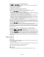
Fixture readouts. . . . . . . . . . . . . . . . . . . . . . . . . . . . . . . . . . . . . . . . . . . . . . . . . . . . . . . . . . . . . . . . . . . 15
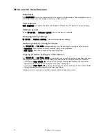
Other control menu features  . . . . . . . . . . . . . . . . . . . . . . . . . . . . . . . . . . . . . . . . . . . . . . . . . . . . . . . . . 15

Operation

. . . . . . . . . . . . . . . . . . . . . . . . . . . . . . . . . . . . . . . . . . . . . . . . . . . . . . . . . . . . . . . . . . . . . . . . . 17

Color control  . . . . . . . . . . . . . . . . . . . . . . . . . . . . . . . . . . . . . . . . . . . . . . . . . . . . . . . . . . . . . . . . . . . . . 17
Stand-alone operation . . . . . . . . . . . . . . . . . . . . . . . . . . . . . . . . . . . . . . . . . . . . . . . . . . . . . . . . . . . . . . 17

Service and maintenance

. . . . . . . . . . . . . . . . . . . . . . . . . . . . . . . . . . . . . . . . . . . . . . . . . . . . . . . . . . 18

Cleaning. . . . . . . . . . . . . . . . . . . . . . . . . . . . . . . . . . . . . . . . . . . . . . . . . . . . . . . . . . . . . . . . . . . . . . . . . 18
Installing and removing the diffuser front. . . . . . . . . . . . . . . . . . . . . . . . . . . . . . . . . . . . . . . . . . . . . . . . 19
Removing and installing LED lenses . . . . . . . . . . . . . . . . . . . . . . . . . . . . . . . . . . . . . . . . . . . . . . . . . . . 20
Fuse replacement  . . . . . . . . . . . . . . . . . . . . . . . . . . . . . . . . . . . . . . . . . . . . . . . . . . . . . . . . . . . . . . . . . 20
Battery service . . . . . . . . . . . . . . . . . . . . . . . . . . . . . . . . . . . . . . . . . . . . . . . . . . . . . . . . . . . . . . . . . . . . 21
Reflector removal. . . . . . . . . . . . . . . . . . . . . . . . . . . . . . . . . . . . . . . . . . . . . . . . . . . . . . . . . . . . . . . . . . 21
Software installation. . . . . . . . . . . . . . . . . . . . . . . . . . . . . . . . . . . . . . . . . . . . . . . . . . . . . . . . . . . . . . . . 21

DMX protocols

 . . . . . . . . . . . . . . . . . . . . . . . . . . . . . . . . . . . . . . . . . . . . . . . . . . . . . . . . . . . . . . . . . . . . 22

All pixels controlled together . . . . . . . . . . . . . . . . . . . . . . . . . . . . . . . . . . . . . . . . . . . . . . . . . . . . . . . . . 22
Pixels controlled in groups. . . . . . . . . . . . . . . . . . . . . . . . . . . . . . . . . . . . . . . . . . . . . . . . . . . . . . . . . . . 23

Onboard control panel menus

. . . . . . . . . . . . . . . . . . . . . . . . . . . . . . . . . . . . . . . . . . . . . . . . . . . . . . 24

Display messages

. . . . . . . . . . . . . . . . . . . . . . . . . . . . . . . . . . . . . . . . . . . . . . . . . . . . . . . . . . . . . . . . . 26

Troubleshooting 

 . . . . . . . . . . . . . . . . . . . . . . . . . . . . . . . . . . . . . . . . . . . . . . . . . . . . . . . . . . . . . . . . . . 27

Stagebar 54™ specifications

 . . . . . . . . . . . . . . . . . . . . . . . . . . . . . . . . . . . . . . . . . . . . . . . . . . . . . . 28

Содержание Stagebar 54

Страница 1: ...Stagebar 54 user manual TM ...

Страница 2: ...ting from Martin Professional A S Information subject to change without notice Martin Professional A S and all affiliated companies disclaim liability for any injury damage direct or indirect loss consequential or economic loss or any other loss occasioned by the use of inability to use or reliance on the information contained in this manual The use of certain patents in Martin Stagebar products i...

Страница 3: ...e from AC power before removing or installing any cover or part and when not in use Always ground earth the fixture electrically Use only a source of AC power that complies with local building and electrical codes and has both overload and ground fault earth fault protection Connect this fixture to AC power either using the supplied power cable or via 3 conductor cable that is rated minimum 20 amp...

Страница 4: ...s must be able to hold at least 10 times the weight of all devices suspended from them and must be installed as described in this manual Check that all external covers and rigging hardware are securely fastened Block access below the work area and work from a stable platform whenever installing servicing or moving the fixture The LED emission presents a hazard to eyesight at a distance of 4 40 cm ...

Страница 5: ...up 13 DMX mode 13 Fixture settings and DMX channel requirements 14 DMX addresses 14 Fixture readouts 15 Other control menu features 15 Operation 17 Color control 17 Stand alone operation 17 Service and maintenance 18 Cleaning 18 Installing and removing the diffuser front 19 Removing and installing LED lenses 20 Fuse replacement 20 Battery service 21 Reflector removal 21 Software installation 21 DM...

Страница 6: ...r to the next fixture The total current draw of all the devices connected to the power outlet of the first fixture in the chain must not exceed 15 amps peak 11 amps constant F Quarter turn mounting points Use to attach the floorstand mounting bracket supplied with the fixture or an omega bracket G Control panel display H Data input connector RJ 45 Connect to DMX control data from the controller or...

Страница 7: ...ints Short Stagebar 54S and long Stagebar 54L models To simplify the combination of different models in installations three short models have the same length as two long models For the latest firmware updates documentation and other information about this and all Martin Professional products please visit the Martin website at http www martin com Comments or suggestions regarding this document may ...

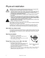
Страница 8: ...an be installed in a standing position or suspended in any orientation from a truss or supporting structure The supplied mounting bracket can be fitted with a rigging clamp or bolted to a surface Alternatively the mounting bracket can be replaced with an omega bracket and rigging clamp Adjustable mounting bracket The adjustable mounting bracket supplied with the fixture can either be folded around...

Страница 9: ...utlet that accepts a light grey PowerCon NAC3FCB cable connector Note that blue input and light grey output connectors have different designs one type cannot be connected to the other You may need to fit the power cable with a power plug that is suitable for your AC power outlets If so install a grounding type earthed plug that is rated 20 A minimum Follow the plug manufacturer s instructions Tabl...

Страница 10: ...ixture draws a current of 2 5 A at 100 V The first fixture will draw a current of 2 5 A The four fixtures linked to the first fixture will draw a total of 10 A which is within the 11 A limit for constant current draw At 230 V AC power a maximum of 11 Stagebar 54 fixtures may be linked in one chain so that they draw AC power from the same source As stated in the Stagebar 54 Specifications see page ...

Страница 11: ...verse must be created before more fixtures can be added The number of Stagebar 54 fixtures that can be individually controlled in one DMX universe depends on the number of DMX channels they use which in turn depends on which mode they are set to For example if fixtures are set to individual pixel control in HSI mode they will each require 18 DMX channels one channel for hue one for saturation and ...

Страница 12: ...op interference ensure that the DMX cable shield does not come into contact with the shell or body of XLR connectors Connecting the data link To connect the data link 1 Cut power to all devices If the luminaire has been in use allow it to cool for at least 10 minutes 2 Connect a suitable cable to the DMX output socket on the DMX controller and route it to the first luminaire on the link 3 Connect ...

Страница 13: ... green color output The intensity of each color is controlled on one DMX channel giving RGB additive color mixing RGBAW red green blue amber white RGBAW is a raw control mode in which the intensity of each color LED is controlled on one DMX channel LED intensity is thus not managed by the fixture software based on its factory settings but is controlled directly by the user The factory settings are...

Страница 14: ...els The first three channels will control hue saturation and intensity on the first 3 pixels and the next three channels will control HSI on the remaining 3 pixels To give another example a fixture in DMX mode RGBAW and pixel grouping set to 2 in which pixels are controlled in three groups of 2 pixels will use 15 DMX channels The first five channels will control RGBAW on the first group of 2 pixel...

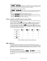
Страница 15: ...ast fixture will refuse to accept the invalid DMX address and will light up red for a moment If you apply an addr input command to a Stagebar 54 you will run the same process but you will assign addresses to all the fixtures that are connected to the first fixture s data input connector The fact that fixtures light up green or red gives an easy visual indication of which fixtures in an installatio...

Страница 16: ...ng fans to run in one of two modes regulated fans are thermostatically controlled giving quietest operation full speed fans run at full speed while power is applied Copying all fixture settings to other fixtures The UT LIT ES cpy fixt setup command lets you save time by setting up one fixture and then copying all that fixture s settings to all the fixtures connected to the data output or data inpu...

Страница 17: ... stand alone operation the Stagebar 54 can be programmed to run two types of display without the need for a DMX controller A static color that you select by adjusting the intensity of the RGBAW pixels Dynamic sequences of RGB RGBAW or pastel colors that you can set to run at fast medium or slow speed Colors cross fade this means that one color fades smoothly into the next with an overlap and each ...

Страница 18: ...ines in this section Cleaning Regular cleaning is essential for fixture life and performance Buildup of dust dirt smoke particles fog fluid residues etc degrades the fixture s light output and cooling ability Cleaning schedules for lighting fixtures vary greatly depending on the operating environment It is therefore impossible to specify precise cleaning intervals for the Stagebar 54 Cooling fans ...

Страница 19: ... install a diffuser front 1 Isolate the fixture from power If the fixture has been in use allow it to cool for at least 10 minutes 2 See Figure 5 Loosen the two captive screws arrowed on the end cap and swing the end cap open 3 Slide the diffuser front into the slots provided in the front of the fixture 4 Close and fasten the end cap before reapplying power To remove a diffuser front 1 Isolate the...

Страница 20: ...mounting posts Fuse replacement Warning Disconnect from power before opening covers Replace fuses with ones of the same type and rating only Primary fuse Stagebar 54 fixtures are protected by a 4 amp slow blow primary fuse located in a fuseholder on the rear panel see Figure 1 on page 6 If a fixture is completely dead apart from the battery powered functions available in the control panel and disp...

Страница 21: ...he DMX data link with the following items The Stagebar 54 main CPU software update file downloadable free of charge from the Support area of the Martin website The Martin Software Uploader program version 5 0 or later downloadable free of charge from the Support area of the Martin website A Martin Universal USB DMX Interface or similar PC fixture hardware interface and Windows PC or a Martin MP 2 ...

Страница 22: ...nnel Value Percent Function 1 0 255 0 100 Red Intensity 0 100 2 0 255 0 100 Green Intensity 0 100 3 0 255 0 100 Blue Intensity 0 100 Start code 0 Channel Value Percent Function 1 0 255 0 100 Red Intensity 0 100 2 0 255 0 100 Green Intensity 0 100 3 0 255 0 100 Blue Intensity 0 100 4 0 255 0 100 Amber Intensity 0 100 5 0 255 0 100 White Intensity 0 100 Start code 0 Channel Value Percent Function 1 ...

Страница 23: ...els required in all the DMX modes available in the Stagebar 54 Start code 0 Channel Value Percent Function 1 0 255 0 100 Hue Red Orange Amber Yellow Green Cyan Blue Indigo Violet Magenta Red 2 0 255 0 100 Saturation Zero white Full saturation 3 0 255 0 100 Intensity Intensity 0 100 4 0 255 0 100 Color Temperature Control 2000 10 000 K Start code 0 Channel Value Percent Function 1 0 255 0 100 Pixel...

Страница 24: ... left to right 1 moved to 6 2 moved to 5 etc off Pixels normal copy dmx mode copy output Copy this fixture s DMX mode to all fixtures linked to data output connector copy input Copy this fixture s DMX mode to all fixtures linked to data input connector STAND ALONE sa setup stand alone off Disable stand alone operation static colour Enable static color display select display intensity from 0 255 fo...

Страница 25: ... highest driver PCB temperature since manufacture temp pixel current Display current average pixel PCB temperature max since reset Display highest pixel PCB temperature since last fixture reset max recorded Display highest pixel PCB temperature since manufacture DMX L NK NFO refresh rate Display DMX signal refresh rate link quality Display DMX signal quality start code Display DMX start code chann...

Страница 26: ...CO D2CO D3CO D4CO D5CO D6CO there is a temperature error on a driver PCB 1 6 identifies the PCB involved CO Cutoff Contact Martin Service for assistance P1CO P2CO P3CO P4CO P5CO P6CO there is a temperature error on a pixel PCB 1 6 identifies the PCB involved CO Cutoff Contact Martin Service for assistance DPER there is a display programming error Contact Martin Service for assistance BALO the batt...

Страница 27: ...or device supplier One or more fixtures displays stand alone sequences incorrectly or not at all Fixtures incorrectly set up Check settings in control menus save time by using the copy settings commands to replicate settings between fixtures Fault on DMX link Inspect connections and cables Correct poor connections Repair or replace damaged cables Incorrect fixture addressing Check number of channe...

Страница 28: ...xing Protocol USITTDMX512 A Stand alone and master slave programming Control panel and display Receiver RS 485 Firmware update Serial upload via DMX link P ho t o m et ri c D a ta Light source Luxeon K2 high power emitters Half peak beam angle 29 consult Martin for availability of optional beam angles Total LED power per pixel 2 x 1 2 W red 2 x 2 9 W green 2 x 2 9 W royal blue 2 x 1 2 W amber 1 x ...

Страница 29: ...840114 User manual P N 35000195 A cc e ss o r i es Neutrik PowerCon NAC3FCA power input connector cable mount blue P N 05342804 Neutrik PowerCon NAC3FCB power output connector cable mount light grey P N 05342805 PowerCon daisy chain power cable 1400 mm 55 in P N 11850099 PowerCon daisy chain power cable 2250 mm 88 5 in P N 11850100 PowerCon daisy chain power cable 3250 mm 128 in P N 11850101 RJ 45...

Страница 30: ...30 Stagebar 54 user manual ...

Страница 31: ...Ø7 Ø9 5 Ø13 5 Ø9 5 Drilling template ...

Страница 32: ......

Отзывы: