


DigiConvert Operating Instructions
Copying this document, or disclosing it to third parties is not allowed without our approval. This document must not be used in any abusive way by the receiver or third
parties. Fe Vogt GmbH
DigiConvert Operating Instructions
74 of 79
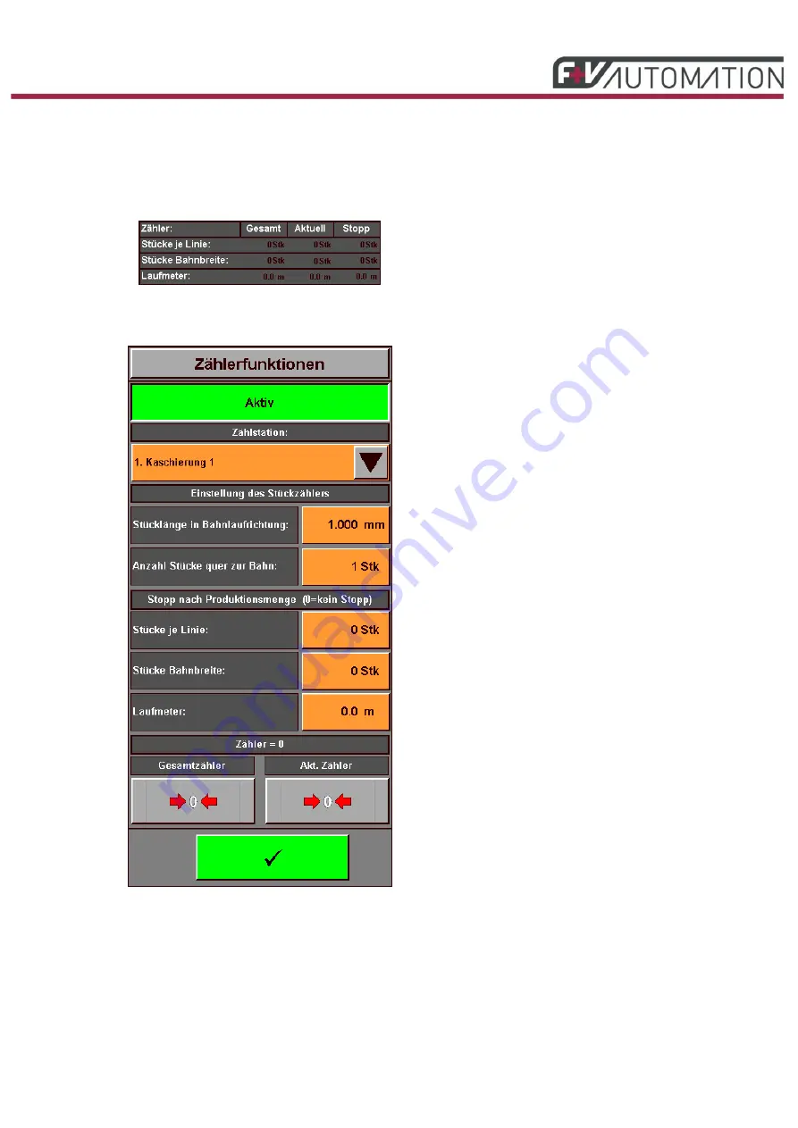
11.7.
Counting Functions Main Menu
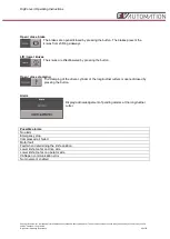
Touch one of the boxes
to open the pop-up window for the counter functions.
Fig.: 27 Counting function