2 - 25
4 - LONGITUDINAL STABILITY ALARM
This device warns the operator that the lift truck is approaching the limit of longitudinal stability. However, lateral stability can
reduce the load char t in the upper par t, and this reduction is not detected by the longitudinal stability alarm.
The operator must always respect the lift truck load chart.
OPERATION
When the lift truck is switched on a control test is automatically carried out.
- Correct operation: All leds and the sound alarm function continuously for 2 seconds.
- Faulty operation: All leds and sound alarm function intermittently (stop the lift truck and consult your dealer, never attempt a
repair yourself).
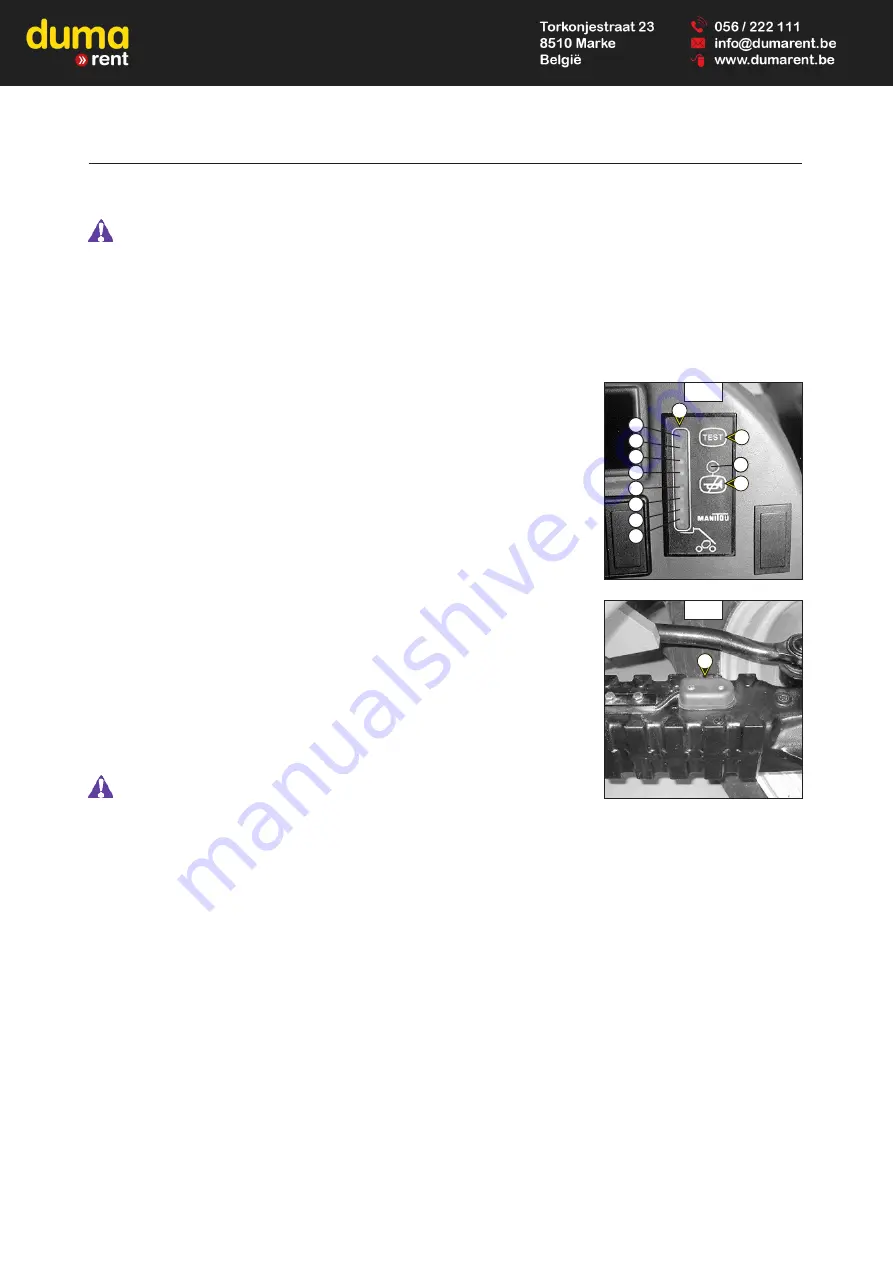
A - LEDS (VISUAL ALARM) (FIG. A)
A1 - 4 green leds: There is a large reser ve of longitudinal stability.
A2 - 2 yellow leds: The lift truck is approaching the limit of longitudinal stability,
move carefully.
A3 - 1 red led: The lift truck is ver y near at the limit of longitudinal stability. The
alarm sounds simultaneously with a slow intermittent sound.
Move ver y carefully.
A4 - 1 red led: The lift truck is at the authorized limit of longitudinal stability. The
alarm sounds simultaneously with a speed intermittent sound.
Only make de-aggravating hydraulic movements in the following
order ; retract and raise the jib.
B - SOUND ALARM SWITCH (FIG. A)
Used to switch off the sound alarm when using the lift truck with loading and ear th moving
buckets. When it is switched off, the red led B1 indicates that the sound alarm has been
cut off and only the visual alarm is working. Under other operating conditions, the sound
alarm must be switched on.
C - TEST SWITCH (FIG. A)
Press the switch to verify at any time that the longitudinal stability alarm is working.
NOTE: This test does not verify that the alarm is correctly set ; this must be checked at
ever y periodic ser vice.
- Correct operation: All leds and the sound alarm function continuously.
- Faulty operation: All leds and the sound alarm function intermittently (stop the lift truck
and consult your dealer, never attempt a repair yourself).
D - STRAIN GAUGE (FIG. B)
Disassembly or adjustment of the strain gauge is prohibited, this must only be done by
specially trained personnel, consult your dealer.
A
B
A2
A1
A1
A1
A1
A2
A3
A4
A
B
B1
C
D
Содержание B-E2 Series
Страница 2: ......
Страница 4: ......
Страница 5: ...1 1 1 OPERATING AND SAFETY INSTRUCTIONS...
Страница 6: ...1 2...
Страница 30: ...1 26...
Страница 31: ...2 1 2 DESCRIPTION 2 DESCRIPTION...
Страница 32: ...2 2...
Страница 47: ...2 17...
Страница 65: ...2 35...
Страница 75: ...3 1 3 MAINTENANCE 3 MAINTENANCE...
Страница 76: ...3 2...
Страница 78: ...3 4...
Страница 97: ...3 23...
Страница 103: ...3 29...
Страница 107: ...3 33...
Страница 109: ...3 35...
Страница 115: ...4 1 4 4 ADAPTABLE ADAPTABLE ATTACHMENTS ATTACHMENTS IN OPTION ON IN OPTION ON THE RANGE THE RANGE...
Страница 116: ...4 2...
Страница 118: ...4 4...
Страница 127: ...4 13...


