4
5
Replacing cylinder liners
113
Checking cylinder liner protrusion
Fig. 4
Clean basic bore and cylinder liner.
Insert cylinder liner without O-rings into crankcase,
observing the marking (ensure that it is identical
with the position prior to removal).
Measure cylinder liner protrusion at at least four
different points, using gauge holder and gauge.
Note:
If available, use measuring plate for the
measurement (special tool, see page 132)
Proceed as follows:
Position press-on measuring plate (1) with
turned collar facing the liner using 2 fitting
sleeves to centre plate.
Tighten 4 bolts (2) (improvised: collar bolt
51.90020-0270, length shortened to 90 mm)
on the press-on measuring plate in stages
and crosswise to 40 Nm.
Set dial gauge combination above press-on
plate to - 0 - under preload relative to the
crankcase.
Measure cylinder liner protrusion at least at
four points.
Fig. 5
Install shim if the protrusion is below the minimum
protrusion even at only one point.
The shim is placed under the cylinder liner collar.
However, it may be used only if after installation
the upper tolerance limit is not exceeded.
3573
Содержание D 2866 LE 401
Страница 1: ......
Страница 17: ...Engine views D 2866 LE401 16...
Страница 18: ...Engine views D 2866 LE401 17...
Страница 19: ...Cross section of engine 18...
Страница 20: ...Longitudinal section 19...
Страница 124: ...123 Special tools...
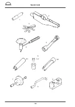
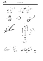
Страница 125: ...Special tools 124 2 3 4 5 6 7 9 1 8 6 1 6 2 6 3...
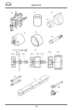
Страница 127: ...Special tools 126 10 11 16 14 14 1 12 13 18 18 1 17 12 1 12 2 15 5 15 4 15 1 15 1 15 2 15 3 15 3 15 6 15 7 15...
Страница 129: ...Special tools 128 21 22 23 25 25 2 24 25 1 26 27 1 27 2 27 20 1 19 2 19 1 20 2 19 20...
Страница 131: ...Special tools 130 29 28 30...
Страница 134: ...Special tools 133 2843 Pressing mandrel for cap dia 50 1 mm Pressing mandrel for cap dia 62 1 mm...
Страница 138: ......


