1
2
3
4
Removing and installing flywheel,
replacing gear ring
62
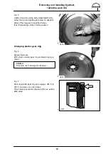
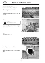
Removing flywheel
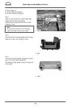
Fig. 1
Loosen mounting bolts (24 mm), securing the en-
gine against turning if necessary.
Note:
Owing to the high initial torque a reinforced
socket (for machine screws) in connection
with a 1/2” tool is required.
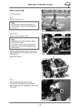
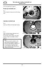
Fig. 2
Remove two bolts facing each other and replace
them by two guide pins (special tool, see
page 127, item. 16).
Remove all bolts.
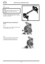
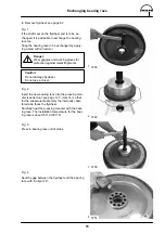
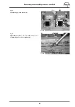
Fig. 3
Pull off flywheel using a flat metal bar and two
bolts M12 x 1.5. Do not tilt it so that it jams.
Caution:
The flywheel is heavy.
Use lifting gear.
Installing flywheel
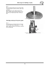
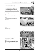
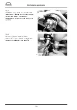
Fig. 4
Screw in guide mandrels
(special tool, see page 127, item 16).
Apply sealing agent ”Antipor 46” to the inside of
the flywheel.
Place guide mandrels on the flywheel, ensuring
that the centering mandrel (arrow) fits correctly into
the bore in the flywheel. Push on flywheel until it
stops.
3466
3675
3468
3676
Содержание D 2866 LE 401
Страница 1: ......
Страница 17: ...Engine views D 2866 LE401 16...
Страница 18: ...Engine views D 2866 LE401 17...
Страница 19: ...Cross section of engine 18...
Страница 20: ...Longitudinal section 19...
Страница 124: ...123 Special tools...
Страница 125: ...Special tools 124 2 3 4 5 6 7 9 1 8 6 1 6 2 6 3...
Страница 127: ...Special tools 126 10 11 16 14 14 1 12 13 18 18 1 17 12 1 12 2 15 5 15 4 15 1 15 1 15 2 15 3 15 3 15 6 15 7 15...
Страница 129: ...Special tools 128 21 22 23 25 25 2 24 25 1 26 27 1 27 2 27 20 1 19 2 19 1 20 2 19 20...
Страница 131: ...Special tools 130 29 28 30...
Страница 134: ...Special tools 133 2843 Pressing mandrel for cap dia 50 1 mm Pressing mandrel for cap dia 62 1 mm...
Страница 138: ......

