5
6
7
Removing and installing injection pump
28
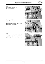
Installing injection pump
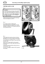
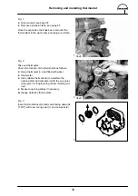
Fig. 5
Important:
If the injection pump is blocked the camshaft
must on no account be loaded or turned be-
cause parts of the blocking pin may break off
and fall into the governor. Non-compliance
with this may result in severe damage to
the injection pump.
Remove screw plug (1) from governor housing.
Take out blocking pin (2) if fitted.
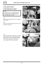
Fig. 6
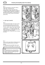
Turn engine to angle for delivery start.
Take cylinder head cover off cylinder no. 6 (fly-
wheel end). When the cylinders are in crossover,
the piston of cylinder no. 1 is at TDC at the end of
the compression stroke.
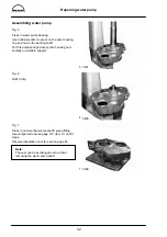
Fig. 7
Check whether the injection pump is in delivery
start position. To do this, remove the screw plug
from the governor housing (see Fig. 5). The deliv-
ery start pointer must be visible in the centre of the
inspection hole.
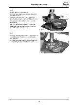
Remove the mounting bolts from the injection
pump drive gear (13 mm) so that it can be turned
in the slots.
Hold injection pump camshaft in place while turn-
ing the gear (41 mm).
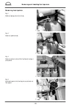
Fit new O-ring (slightly coated with oil) to injection
pump flange.
1
2
2310
3390
3400
Содержание D 2866 LE 401
Страница 1: ......
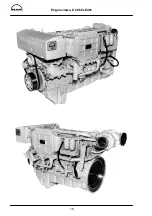
Страница 17: ...Engine views D 2866 LE401 16...
Страница 18: ...Engine views D 2866 LE401 17...
Страница 19: ...Cross section of engine 18...
Страница 20: ...Longitudinal section 19...
Страница 124: ...123 Special tools...
Страница 125: ...Special tools 124 2 3 4 5 6 7 9 1 8 6 1 6 2 6 3...
Страница 127: ...Special tools 126 10 11 16 14 14 1 12 13 18 18 1 17 12 1 12 2 15 5 15 4 15 1 15 1 15 2 15 3 15 3 15 6 15 7 15...
Страница 129: ...Special tools 128 21 22 23 25 25 2 24 25 1 26 27 1 27 2 27 20 1 19 2 19 1 20 2 19 20...
Страница 131: ...Special tools 130 29 28 30...
Страница 134: ...Special tools 133 2843 Pressing mandrel for cap dia 50 1 mm Pressing mandrel for cap dia 62 1 mm...
Страница 138: ......


