background image

Mammoth Fans COMMERCIAL II SERIES     |      

13

12

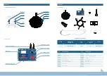
DESCRIPTION OF COMMON PARAMETERS OF CONTROL SYSTEM

USER SETTING INTERFACE DESCRIPTION

FAN INSTALLATION

ELECTRICAL WIRING DIAGRAM

15. DEBUGGING

Each Mammoth Fan is tested prior to leaving the factory. If there seems to be a problem  
double check all electrical connections, and contact the Mammoth support team.

16. COMMISSIONING

Use a spirit level and ensure blades are level before switching on. Run the fan for 15mins  
and observe, is it spinning in the correct direction (anti-clockwise for summer), listen for any 
abnormal noise, ensure there is no movement in the support cables. Check the current is  
within the rated range.

17. HANDOVER

Ensure the customer is instructed on how to operate and isolate the fan.

LCD DISPLAY STATUS CONFIRMATION

OPERATING INTERFACE

ACCELERATING INTERFACE

STANDBY INTERFACE

SETTING INTERFACE

DECELERATING INTERFACE

FAILURE INTERFACE

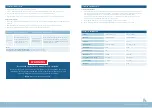
FUNCTION CODE

DESCRIPTION

EXPLANATION

S00

Return

Function can be used to return to the main interface. If it doesn’t return by this 
function, it will automatically return to the main interface after 10s.

S01

Rotating speed 
unlocked/
rotating speed 
locked

Once locked, the adjusting knob will not change the given rotating speed to 
prevent accidental touching. Select this function again to unlock the rotating 
speed.

S02

Motor  
self-learning

Function can be used to improve motor operation control.

S03

Operation  
direction switch

If the motor runs in the wrong direction, the motor direction can be switched 
by this function.

After the controller is powered on, when the switch points to ON, the machine is powered on, and the LCD displays: given rotating 
speed, operating current, input voltage, operating status, whether “output rotating speed” is locked, failure interface and other 
specific interface information as follows. Note: Interface is preset to English.

In the standby state, long press the knob (more than 2 seconds) to enter the ‘setting interface’. The setting interface functions are 
as follows:

Содержание COMMERCIAL II Series

Страница 1: ...114 07 C A U T I O N R E A D I N S T R U C T I O N S C A R E F U L LY F O R S A F E I N S T A L L A T I O N A N D F A N O P E R A T I O N C O M M E R C I A L I I S E R I E S I N S TA L L AT I O N O PE...

Страница 2: ...ensure that they do not play with the appliance 6 An all pole disconnection switch must be incorporated into the fixed wiring in accordance with local wiring rules 7 The structure to which the fan is...

Страница 3: ...m cover 5 Aluminium alloy bushing 12 Blade components 6 Coil of wire 13 Extension tube 7 Fan controller CASE NO DIMENSIONS LxWxHmm Volume m3 Gross weight kg Remark 1 1400 x 600 x 310 0 16 70 Main body...

Страница 4: ...Exclusively distributed by Beacon Lighting 7 6 5 Required installation tools PARTS LIST ADJUSTABLE WRENCH LASER DISTANCE MEASURE ALLEN KEYS WIRE CUTTER SOCKET WRENCH LEVEL MULTIMETER SCREW GLUE...

Страница 5: ...r to the below diagram for detailed spacing requirement Secure the hanging bracket to the ceiling joist or structure with provided bolts and nuts Ensure there are 3 4 threads left on the bolt after ti...

Страница 6: ...propriate electrical connection to the fan body ensure neat and tight connections are completed NOTE This is the steel wire bracket Please make sure it is installed before installing the fan motor par...

Страница 7: ...FACE FUNCTION CODE DESCRIPTION EXPLANATION S00 Return Function can be used to return to the main interface If it doesn t return by this function it will automatically return to the main interface afte...

Страница 8: ...s this could damage the fan and cause a safety issue 3 Ensure that the fitting does not come in contact with any organic solvents or cleaners 4 The motor has a permanently lubricated ball bearing whic...

Страница 9: ...overcurrent fault Overload Reducing load or replacing impulse load of large capacity controller requires reducing load change frequency or replacing larger capacity controller Short circuit to the out...

Страница 10: ...ncrease Torque lift set too large Decrease F04 01 torque increase V F curve setting is not appropriate To determine the relationship between voltage and frequency of V F curve setting modify F04 00 VF...

Страница 11: ...arning If the error still occurs contact the Mammoth Fan support team Note where xx is self learning faults ub code Code Desc Reason Solution E oUxx Mid acceleration moderate midspeed stop over voltag...

Страница 12: ...major failure Mammoth Fans cannot be held responsible for any repair other than those carried out by it or one of its Authorised Service Agents Please keep this warranty information in a safe place Th...

Страница 13: ...C O M M E R C I A L I I S E R I E S...

Отзывы: