Mammoth Fans COMMERCIAL II SERIES |
17
16
TROUBLESHOOTING
TROUBLESHOOTING
Common causes of operation malfunction
1.
Ensure that the external power supply of the control box is within the range appropriate for the controller.
2.
Ensure that there is power to the controller box and turn the speed dial to the minimum setting (Slow). Then turn the control
dial to Run. If this doesn’t work, turn the control dial to Reset, then to Stop and finally to Run.
3.
If on startup you notice any unusual sounds coming from the fan or the controller immediately return the control dial to Stop
and contact the Mammoth support team.
4.
Equipment damage due to improper use is not covered by the warranty. Mammoth Fans will not be responsible for personal
injuries and equipment damages for failure to comply with the contents of this manual.
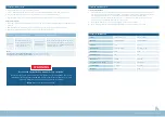
Code
Desc.
Reason
Solution
E.Lu
Under
pressure in
operation
Power outages or
instantaneous power outages
Check power and reset
Input power lack phase
Confirmation of main circuit wiring
Excessive input voltage
fluctuations
Improve the power supply to meet the rated voltage of
the controller. If the main circuit power supply is fine,
check the main circuit side of the electromagnetic con-
tactor to identify the problem
Note:
this fault is detected when the bus voltage is lower than the ** voltage protection point (F10.19) when the controller is running.
Code
Desc.
Reason
Solution
E. oCxx
Mid
acceleration/
mid
acceleration/
mid
speed/
overcurrent
fault
Overload
Reducing load or replacing impulse load of large
capacity controller requires reducing load change
frequency or replacing larger capacity controller
Short circuit to the output
side of the controller
Check main circuit, eliminate short circuit
Motor damaged
Measure the resistance between the lines of the motor
and replace the motor immediately if conducting
Too short acceleration/
deceleration time
Increase F01.22 (acceleration time 1) increase F01.23
(deceleration time 1) replace bulk control
Overvoltage suppression of
rising frequency may result
in accelerated overcurrent
fault
Decrease overvoltage gain F10.13
Overflow suppression of
frequency reduction
resulting in decelerated
overcurrent fault
Increase overcurrent suppression gain F10.02
Controller output cable
exceeds allowable
maximum
Shorten output cable or add sinusoidal filter
Misoperation caused by
interference
Check the wiring of control circuit, main circuit and
ground, remove interference source
Note:
this fault is detected when the output current of the controller exceeds the overcurrent point.
ER Code
Description
E. oC1/E. oC2/E. oC3
Acceleration/deceleration/constant speed/overcurrent
E. oU1/E. oU2/E. oU3
Acceleration/deceleration/constant speed/overvoltage
E. Lu
Undervoltage during operation
E. oCxx
Mid acceleration/mid acceleration/ mid speed/ overcurrent fault
E. oL1
Motor overload
E. oL2
Controller overload
E. iLF
Input phase loss
E. oLFxx
U/V/W phase output phase loss
E. oH2
IGBT module over temperature
E. oUxx
Mid acceleration/ moderate/ midspeed/ stop/over voltage fault
E. TExx
Self-learning output current exceeds limit
E. SPD
Rapid failure
Содержание COMMERCIAL II Series
Страница 13: ...C O M M E R C I A L I I S E R I E S...


