[3] DISASSEMBLY/ ASSEMBLY
[3]-1. Motor section (cont.)
R
epair
P
8
/
18
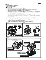
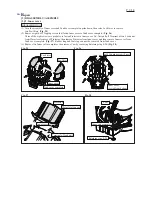
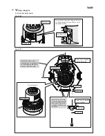
(11) Install two Outer valve completes in place as shown in
Fig. 22
.
Note:
Be careful not to move them out of place when installing Separator complete in step (13) below.
(12) Assemble DC motor unit. [Refer to step (6) and
Fig. 6
of "DIS
ASSEMBLING
".]
Note:
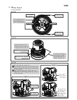
When installing DC motor on Gear case, insert the positioning pin of Gear case into the positioning hole of
DC motor. (
Fig. 23
)
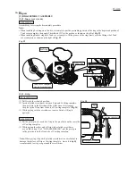
(13) Put Separator complete on Tank cover complete, then put DC motor unit in place; at this time, do not forget to
engage the two flats of Spindle with those of Cam’s hole.
Note:
Do not forget to place DC motor seal between Separator complete on Tank cover complete.
Note:
Apply Makita grease N.No.2 to the gear chamber of Gear case to prevent Spindle assembly from falling off
from DC motor unit.
(14) Fasten Separator complete and DC motor unit to Tank cover complete with seven 4x35 Tapping screws,
then insert Vinyl tube into place. [Refer to
Fig. 4
of "DIS
ASSEMBLING
".]
(15) Fit Switch base E-M complete in Cowling complete, then put Cowling complete over Separator complete;
be sure to fit the top end of Switch base E-M complete in the groove inside Cowling complete to prevent
Switch base E-M complete from falling out of place. (
Fig. 24
)
And then fasten Cowling complete to Separator complete with nine 4x35 Tapping screws.
ASSEMBLING
Fig. 23
Fig. 22
Fig. 24
Tank cover complete
Outer valve complete (2pcs)
positioning pin
positioning hole
Gear case
DC motor
Cowling complete
Separator complete
Switch base E-M complete
groove inside
Cowling complete
top end of
Switch base E-M complete
Cowling complete,
viewed from bottom
groove inside
Cowling complete

