background image

[3] DISASSEMBLY/ ASSEMBLY

[3]-5. Bumper

R

epair

P 1

2

/

18

Assemble by reversing the disassembly procedure.

Pry Bumper off from Tank with a slotted screwdriver. (

Fig. 36

)

ASSEMBLING

DISASSEMBLING

Note:

 Make sure that there is no gap between Bumper and Base.

Fig. 36

Tank

Bumper

[3]-6. Inlet section

Install the parts of Inlet section onto Tank as shown in 

Fig. 37

.

ASSEMBLING

Note:

 Make sure O ring 56 is installed on Holder before installing

Inlet onto Holder.

Fig. 37

Tank

Inlet

O ring 56

Holder

4x28 Tapping screw (3 pcs)

Holder plate

[3]-7. Checking automatic self-cleaning filter system

After repair is complete, be sure to check if the automatic

self-cleaning system works properly as follows:

(1) Turn Motor section upside down and place it on a workbench

      as shown in 

Fig. 38

.

(2) Switch on the machine.

(3) Make sure that two Filter units collapse then expand

      alternately every 10 seconds.

Fig. 38

Filter unit

Содержание VC3211M

Страница 1: ...Cap 1 Poly bag 800x650 1 Poly bag set 1 incl 10 pcs of Poly bag 800x650 2 0 1 3 5 2 22 0 Max sealed suction kPa Max air flow m minute Yes Power tool activation M Dust class in accordance with the EU s...

Страница 2: ...x 1R276 V Block 1R258 press fitting Fan cover onto Return vane Repair Retaining ring S and R pliers 1R291 removing installing Retaining rings Torque driver 1R344 tightening M5x60 Pan head screws throu...

Страница 3: ...ews fastening DC motor unit to Tank cover complete Fig 4 6 Remove DC motor unit from Tank cover complete Fig 5 Note Be careful not to drop Spindle assembly out of DC motor unit DC motor unit can be di...

Страница 4: ...ver from AC motor unit then remove Fan 62 by turning it clockwise fast by hand If Fan 62 cannot be removed by hand turn it by pushing the fan blade with a small slotted screwdriver as shown in Fig 9 N...

Страница 5: ...mmer 14 Remove Fan 125 from Armature shaft as follows hold Armature firmly with a gloved hand then remove M8 Hex nut by turning counterclockwise with an impact driver 15 Remove Return vane from Base a...

Страница 6: ...ess fit Fan cover onto Return vane Fig 16 3 Push Rubber ring 120 firmly into the groove of Base with the groove side up as shown in Fig 17 Note When installing Separator complete in step 13 of ASSEMBL...

Страница 7: ...ghten Fan 62 hand tight by turning it counterclockwise and then tighten securely by pushing the fan blade with a small slotted screwdriver Fig 19 Note Be careful not to deform the fan blade with the s...

Страница 8: ...chamber of Gear case to prevent Spindle assembly from falling off from DC motor unit 14 Fasten Separator complete and DC motor unit to Tank cover complete with seven 4x35 Tapping screws then insert Vi...

Страница 9: ...al of two Lead units from Water level sensors of Protector then remove Protector from Inner cover and then remove Inner cover from Tank cover complete Fig 27 Rubber ring and Seal ring can now be remov...

Страница 10: ...ying the other end of Grip with a slotted screwdriver as you did in step 3 of DISASSEMBLING put the pivot pin in the pivot hole on the front side of Cowling complete 1 Put Grip in the retracted positi...

Страница 11: ...1R263 as follows 1 Insert the M shaped end of two Bearing extractors 1R263 between the slit you made in step 2 2 Hold the metal stem of Caster 75 with the M shaped end as shown in Fig 32 3 Pry Caster...

Страница 12: ...ig 37 ASSEMBLING Note Make sure O ring 56 is installed on Holder before installing Inlet onto Holder Fig 37 Tank Inlet O ring 56 Holder 4x28 Tapping screw 3 pcs Holder plate 3 7 Checking automatic sel...

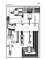
Страница 13: ...yellow or green black or brown Impedance protection circuit Lead unit Lead unit Receptacle may vary by country see next page for details Terminal block Pressure sensor DC motor Buzzer circuit Switch S...

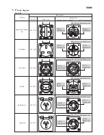
Страница 14: ...C3 are located Receptacle C01 to Orange wire C02 to Purple wire C03 to Green and Yellow wire C02 to Purple wire C03 to Green and Yellow wire C01 to Orange wire C02 to Purple wire C03 to Green and Yell...

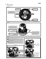
Страница 15: ...the exit of the wire Fix two Field lead wires to each Brush holder in these lead wire holders Fig D 05 WRONG The slack of the pig tail wire is out of place The pig tail wire is not running right due...

Страница 16: ...der pig tail wire of Carbon brush Be careful not to pinch the pig tail wire of Carbon brush between Motor cover and Brush holder Band cable tie AC motor unit Band cable tie Tank cover complete viewed...

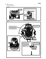
Страница 17: ...ed marking Push Vinyl tube over this boss firmly until it stops Route AC motor s lead wires through this opening of Separator complete make sure that they are tight inside Separator complete Connect F...

Страница 18: ...eptacle with Receptacle sleeve Receptacle Switch Sub controller Switch Connect Receptacles to Switch as shown below Do not place the slack of Lead wires on these ribs Do not place the slack of Lead wi...

Отзывы: