27 ENGLISH
(a) (b)
(c) (d)
1
2
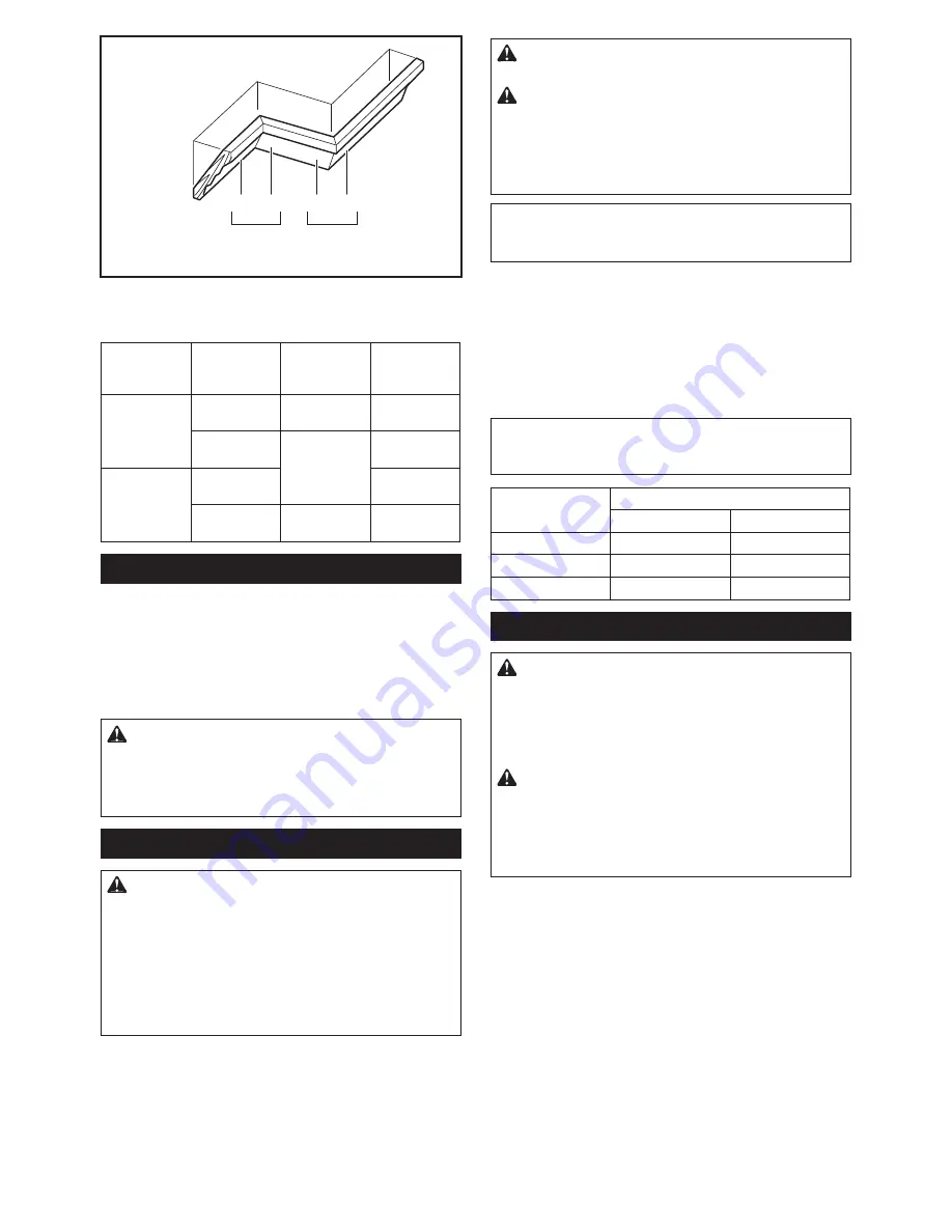
1.
Inside corner
2.
Outside corner
Table (C)
–
Molding
position in
] )^<()
Miter angle
Finished
piece
For inside
corner
(a)
Right 45°
Save the right
side of blade
(b)
Left 45°
Save the left
side of blade
For outside
corner
(c)
Save the right
side of blade
(d)
Right 45°
Save the left
side of blade
Cutting aluminum extrusion
j
Fig.52:
1.
Vise
2.
Spacer block
3.
Guide fence
4.
#^
5.
Spacer block
When securing aluminum extrusions, use spacer blocks
J
deformation of the aluminum. Use a cutting lubricant
when cutting the aluminum extrusion to prevent build-up
of the aluminum material on the blade.
WARNING:
Never attempt to cut thick or
round aluminum extrusions.
Thick or round alumi-
^ J A
may loosen during the cutting operation which may
Wood facing
WARNING:
Use screws to attach the wood
facing to the guide fence. The screws should be
installed so that the screw heads are below the
y<([#\)Y[]
)|YY[#\'.^yY]
#]]
):|'%%.Y]
interfere with the positioning of the material being
cut.
Misalignment of the material being cut can case
unexpected movement during the cutting operation
which may result in a loss of control and serious
CAUTION:
Use straight wood of even thick-
ness for the wood facing.
CAUTION:
.Y()(]Y\YjX%)])%:\<]] (Y<^
workpieces with a height of
107
mm to
120
jj#
wood facing should be used on the guide fence.
The wood facing will space the workpiece away from
the fence allowing the blade to complete a deeper
cut.
NOTICE:
).] )|YY[#\'.^'y#]]#\ )Y
not turn the turn base with the handle lowered.
The blade and/or the wood facing will be damaged.
Use of wood facing helps to assure splinter-free cuts
J A#J
using the holes in the guide fence and 6 mm screws.
-
gested wood facing.
j
Fig.53:
1.
Hole
2.
Over 15 mm
3.
Over 270 mm
4.
90 mm
5.
145 mm
6.
19 mm
7.
115 -
120 mm
EXAMPLE
When cutting workpieces 115 mm and
120 mm high, use a wood facing with the following
thickness.
Miter angle
Thickness of wood facing
115 mm
120 mm
0°
20 mm
38 mm
Left and Right 45°
15 mm
25 mm
Left and Right 60°
15 mm
25 mm
Groove cutting
WARNING:
Do not attempt to perform this
]:X)Y[\<];:<y'.^#|')(]:X);%#)Y(#Y
blade.
#A JJ
blade or dado blade could lead to unexpected cutting
results and kickback which may result in serious
WARNING:
Be sure to return the stopper arm
to the original position when performing other
than groove cutting.
#AJ
the stopper arm in the incorrect position could lead to
unexpected cutting results and kickback which may
For a dado type cut, perform as follows:
1.
#J
J -
ting depth of the blade. Refer to "Stopper arm" section
described on previously.
2.
# J
cut parallel grooves across the width of the workpiece
using a slide (push) cut.
j
Fig.54:
1.
Cut grooves with blade
3.
Remove the workpiece material between the
grooves with a chisel.
Содержание LS1219
Страница 2: ...Fig 1 10 11 12 14 15 3 2 4 5 8 7 9 13 6 1 16 17 18 19 20 21 Fig 2 2 ...
Страница 3: ...7 8 5 6 1 2 3 4 9 10 11 15 13 12 14 Fig 3 1 2 Fig 4 1 3 2 4 Fig 5 3 ...
Страница 4: ...1 3 2 Fig 6 1 Fig 7 1 Fig 8 3 1 2 Fig 9 1 Fig 10 1 2 3 4 6 5 Fig 11 4 ...
Страница 5: ...1 Fig 12 1 Fig 13 1 3 2 Fig 14 1 2 Fig 15 1 3 2 4 Fig 16 1 Fig 17 5 ...
Страница 6: ...1 Fig 18 1 2 Fig 19 1 Fig 20 1 Fig 21 1 Fig 22 3 2 1 Fig 23 1 2 3 Fig 24 6 ...
Страница 7: ...1 Fig 25 1 Fig 26 A B Fig 27 1 Fig 28 3 1 2 Fig 29 7 ...
Страница 8: ...3 1 2 Fig 30 2 3 1 4 5 Fig 31 1 2 Fig 32 1 2 3 4 5 6 Fig 33 3 1 2 Fig 34 8 ...
Страница 9: ...1 2 Fig 35 1 Fig 36 1 2 Fig 37 1 2 4 3 2 1 3 4 Fig 38 2 3 1 Fig 39 1 2 3 4 Fig 40 9 ...
Страница 10: ...1 2 3 Fig 41 2 1 Fig 42 1 Fig 43 1 Fig 44 Fig 45 10 ...
Страница 11: ...1 2 3 Fig 46 1 2 3 Fig 47 2 3 1 4 Fig 48 1 2 3 4 Fig 49 1 4 2 3 Fig 50 2 1 Fig 51 11 ...
Страница 13: ...1 Fig 60 2 1 Fig 61 1 2 3 Fig 62 Fig 63 1 2 Fig 64 13 ...
Страница 14: ...4 5 1 3 2 Fig 65 1 4 2 3 5 Fig 66 1 2 Fig 67 1 Fig 68 1 Fig 69 14 ...


