R
epair
P 6 / 14
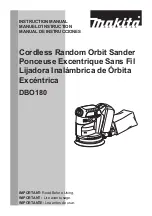
3. After taking off balancer, tighten the hex socket head bolt M5x16 again loosely. And slightly hit this
hex socket head bolt. Then base can be separated from frame. See Fig. 4.
Fig. 4
Frame
Base
Bottom view of base
Hex socket head
bolt M5x16
Bottom view of base
Hex wrench with which hex socket head bolt M5 x 16
can be fastened.
Screwdriver
Rib
Balancer
< 3 > Assembling base section
1. Make sure that 4 pcs. of foot has been assembled to the correct positions, before assembling base. See Fig. 5.
Fig. 5
4 pcs. of foot
2. Lock balancer with screwdriver inserted at the rib of base, and fasten hex socket head bolt M5 x 16 with
hex wrench, or with impact driver. Then balancer can be assembled to base. See Fig. 6.
Fig. 6
Base
< Note >
The hex socket head bolt M5 x 16 is an adhesive screw.
Do not fasten the base with the used bolt. Replace with
the fresh adhesive hex socket head bolt M5 x 16.
3. Assemble under cover with aligning its slit with the guide rib of base as illustrated in Fig.7.
4. Assemble O ring 75 by pushing it with screwdriver into the space between under cover and the wall of base.
See Fig. 7A.
Fig. 7
O ring 75
Under cover
Wall of frame
Guide rib of base
Slit
Under cover
Frame
Fig. 7A