


33
Patching into a jack to override a normalization does a lot to open up the signal flow possibilities in the 0-Coast. The concepts
already outlined can get you very far, but as you continue patching, some questions will eventually start to arise: What if you
want to control a parameter with two sources at once? What if you want to send the same modulation source to more than
one destination? What if you want to control a positive-only parameter like OVERTONE with a negative version of a
positive-only signal like CONTOUR?
The Voltage MATH, located below the CLocK and Random circuits, is a small, powerful, open-ended circuit that provides the
answers to questions like these. It gives a small taste of the sorts of Control Processing that can be done in our modular
systems using modules like MATHS. The concepts of Sum, Difference, Offset, Inversion, Attenuation, Amplification, and
Multing are all represented here.
The short and technical way to describe the Voltage MATH is:
- The two signal Inputs are Summed, and the result appears at each of the signal Outputs.
- The right-hand signal input is normalled to an Offset, and is equipped with an attenuverter.
If that reads more like science than music, here is a slower, less technical description with examples:The two inputs at the top
are mixed (Summed) together. The result appears identically at both outputs at the bottom. The left input, CHannel 1, is
always at "Unity" (there is no control over its Level or polarity), while the right input, CHannel 2, is further processed by an
attenuverter. (
See Page 18
)
An example of the use of mixing, or Summing, the two inputs, would be randomizing the start point of modulation of the
MULTIPLY circuit by the SLOPE circuit. To do this, patch SLOPE to the left input, RANDOM to the right input, and either of the
Control Processor outputs to MULTIPLY CV Input .Set the Control Processor's right input attenuverter to 12:00. Set MULTIPLY
full counterclockwise and the MULTIPLY CV Input attenuverter to about 3 o’clock. You should hear the familiar sound of the
MULTIPLY circuit being modulated by SLOPE (remember to have BALANCE set far enough clockwise that the OVERTONE
circuit is audible). Gradually turn the Control Processor's input attenuverter clockwise to hear Random voltage added to the
SLOPE's output. You could also try syncing this Random voltage to the SLOPE generator by patching the EOC output to the
TEMPO input, which will cause a new Random value with each Cycle of the SLOPE.
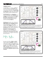
FIGURE 66: Voltage MATHs
FIGURE 67: CH. 1+2
+10V
-10V
CH2
CH1
SUM OUT:
The SUM OUTput is a voltage mixer, allowing
for the easily addition or subtraction of two signals of any
type. With nothing patched to CH.2, the Panel Control acts
generates an Offset.
Time
0V
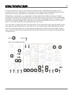
FIGURE 68: SUM BUS
+5V
-5V
SUM
SUM
OUTPUT:
Time
0V
CH1
CH2
Содержание 0-Coast
Страница 1: ...5 19 16 REV 7 v 1 16...
Страница 9: ...8 Figure 8 Default Sound Figure 9 Drone...


