


26
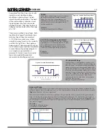
Amplitude and Brightness
CONTOUR (cont’d)
With
SUSTAIN
set to Full clockwise,
SUSTAIN
is
maximum, but with no audible
DECAY
, as the
circuit remains at the Maximum level.
Figure 53
is
a 3 Stage function, operating as an
ASR
, or
Attack
Sustain Release
envelope. Many older electronic
organs utilized this type of Amplitude control.
With
SUSTAIN
settings anywhere between
Minimum and Maximum, the
CONTOUR
generates
a 4-Stage function that, when used to drive the
DYNAMICS
circuit, produces the classic
“ADSR,”
or
Attack, Decay, Sustain Release
Amplitude
Envelope, as popularized by the East Coast
Synthesis technology
(Figure 54).
Vari-Response
shapes these rates of change (i.e.
ONSET/ DECAY
) to be Linear, Exponential, and
everything inbetween. With
EXPO
response, the
rate of change INCREASES as the voltage
INCREASES. With a
LINEAR
response, there is no
change in rate when the voltage is changing . The
Vari-Response
control may be used to increase or
decrease the overall time or speed of the
CONTOUR
. Setting
Vari-Response
more
Clockwise in order to be more Exponential
increases the rate, causing the 0-COAST to sound
more percussive. Setting it to be more LINEAR
decreases the rate, causing the 0-COAST to fade in
and out of existence.
Experiment with different
ONSET
and
DECAY
settings, while leaving
SUSTAIN
set to about 11
o’clock, and Vari-Response set to 2 o’clock. This
may help you understand what
ONSET
and
DECAY
are doing. Now, set
ONSET
to 9 o’ clock, and
DECAY
to 3 o’ Clock, while experimenting with
different
SUSTAIN
settings. Finally, experiment
with different
Vari-Response
settings using the
Panel Controls to change the shape and rate of the
CONTOUR
.
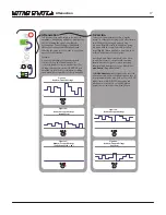
(ONSET)
ATTACK
(DECAY)
RELEASE
SUSTAIN
ONSET (Attack) Sustain DECAY (Release) (ASR):
Once the Gate is received at the CONTOUR GATE
Input, the FUNCTION Rises at a Rate and Shape set by the ONSET and VARI-RESPONSE Panel Controls
and increases until it hits its maximum value of 8V. Next, the SUSTAIN circuits alter the Function
according to the SUSTAIN Panel Control. Finally, the Function “Releases” back to 0V at a Rate and
Slope determined by the DECAY and Vari-Response Panel Controls.
Time, in Seconds
+10V
0V
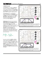
Figure 53:
ATTACK
RELEASE
DECAY
Attack Decay Sustain Release (ADSR):
Once the Gate is received at the Contour GATE Input, the
FUNCTION Rises at a Rate and Shape set by the ONSET and Vari-Response Panel Controls and
increases until it hits its maximum value of 8V. Next, the Decay and Sustain circuits alter the
Function according to the Contour Circuit Panel Controls. Finally, the Function “Decays” back to 0V at
a Rate and Slope determined by the Vari-Response Panel Controls.
Time, in Seconds
+10V
0V
Figure 54:
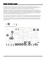
SUSTAIN
EXPONENTIAL
LINEAR
(ONSET)
(DECAY)
Содержание 0-Coast
Страница 1: ...5 19 16 REV 7 v 1 16...
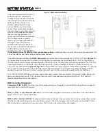
Страница 9: ...8 Figure 8 Default Sound Figure 9 Drone...


