


18
Attenuversion
An example user for the Attenuverter on the Control Processor’s CH.2 INput is
patching a variable depth Vibrato. If you patch a Cycling SLOPE directly to the 1V/Oct
input on the Oscillator, you get a vibrato, but with a range of many octaves. Instead,
try patching it to the right input of the Control Processor, take either output to 1V/oct,
and adjust the Depth using the CH. 2 attenuverter. With this patch you can still
control the pitch of the Oscillator using the MIDI In. The other output is identical to
the first, so you could control modulation Depth from SLOPE to two different
parameters at once using the single Attenuverter.
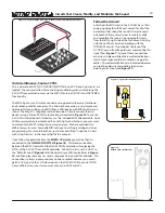
If nothing is patched to the left input, it is disregarded. If nothing is patched to the
right input, it is Normalled to an Offset, which can also be attenuverted. The perfect
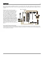
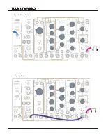
example of using this offset by itself is the Default Sound Drone patch,
Figure 9
. In
this patch, the offset is patched to the Dynamics circuit to allow sound to pass
through at all times.
As mentioned above in (1), the left input is always at "Unity" (there is no control over
its amplitude), while the right input comes with an attenuverter. An example of the
usefulness of inverting a signal: say you want to have the value of Overtone go lower
as Contour goes higher, so it is modulated by Contour in the opposite direction from
the Dynamics circuit. To do this, you could set Overtone full clockwise, patch Contour
to the CH.2 input, set the CH.2 attenuverter full counterclockwise (as in
Figure 31
) ,
patch its output to the Overtone CV input, and set the OVERTONE CV Attenuator Full
CW.
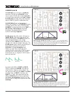
Since the two outputs are identical to each other, the Control Processor is also a
multiple and can be used to send one signal to two destinations. Just patch to the
right input and turn the attenuverter all the way clockwise, and you have two
identical outputs available. If the signal you are patching is also normaled somewhere,
it could be sent to a total of three destinations. For example, Slope could be patched
to MULTIPLY (via normalization), Balance, and Overtone all at once.
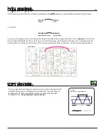
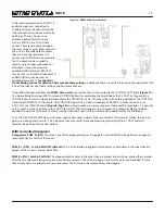
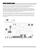
+10V
0V
Figure 30:
Random Stepped Voltage
Time
+10V
-10V
Figure 31:
Random Stepped Voltage Attenuverted
Time
0V
Содержание 0-Coast
Страница 1: ...5 19 16 REV 7 v 1 16...
Страница 9: ...8 Figure 8 Default Sound Figure 9 Drone...


