


Oscillator
Set 0-COAST to the “Default Sound” (
Figure 8, Page 8)
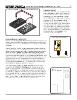
. To hear how the OSCILLATOR works, it is helpful to either hold a key
down on your controller, or to set the 0-COAST to Drone, as shown in
Figure 9
.
The voice of the 0-COAST begins at this circuit: a Triangle core,
voltage-controlled oscillator (VCO
) that generates two
waveforms: Triangle and Square, as illustrated in
Figure 39
. The
OSCILLATOR
is the primary sound source of the 0-COAST. Set
BALANCE
to Full CCW so that it is passing the internally-routed
Triangle waveform signal.
Within the
BALANCE
circuit, we refer to this as the
FUNDamental
.
The Triangle waveform has so few audible Overtones, it is nearly a
pure representation of our single Fundamental frequency, which is
determined by the PITCH Panel controls, MIDI, and CV patched to
1V/ Octave Input. The sound of the Triangle is smooth and pure.
The Triangle waveform is often used as the starting point for West
Coast synthesis techniques.
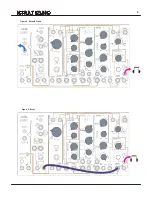
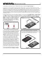
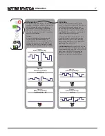
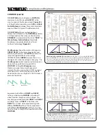
Now, grab a patch cable and patch the Square OUT from the
OSCILLATOR
circuit to the BALANCE Ext. IN,
Figure 38
.
Be sure the BALANCE Panel Control is still set to Full CCW. You
should now be hearing the Square waveform, which has many
audible Odd Overtones, making it more rough and complex. This
gives it a hollow aggressive sound. The Square waveform is often used as the starting point for East Coast synthesis
techniques. These two waveforms: Triangle and Square, are wonderful sounds. You may manually control the pitch using
the PITCH Panel Controls Coarse and Fine for immediate physical control of Pitch, just like on a modular synthesizer. You may
also control the OSCILLATOR PITCH using the MIDI INput or patching a CV signal to the 1V/Octave CV IN. Try controlling the
pitch of the OSCILLATOR in these ways and comparing how the Square and Triangle waveforms sound at different pitches,
high and low frequency.
20
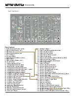
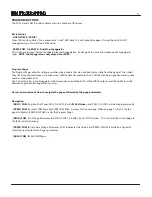
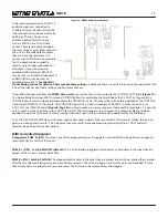
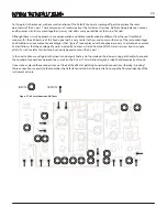
1. PGM A Illuminated Button <white>
2. MIDI A Activity Window <red>
3. MIDI INput Jack
4. MIDI B Activity Window <red>
5. Ext. CV OUTput
6. Ext. Gate OUTput
7. PGM B Illuminated Button <white>
8. TEMPO INput
9. TEMPO Activity Window <red>
10. CLocK OUTput
11. Stepped Random OUTput
12. Voltage MATH: CHannel 1 INput
13. Voltage MATH: CHannel 2 INput
14. Voltage MATH: CHannel Attenuvertor
15. Voltage MATH: Activity Window <red> / <green>
16. Voltage MATH: CHannel 1 OUTput
17. Voltage MATH: CHannel 2 OUTput
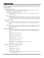
18. Oscillator: Triangle Wave OUTput
19. Oscillator: Square Wave OUTput
20. Oscillator: Pitch Panel Control
21. Oscillator: Pitch Fine Tune
22. Oscillator: LINear FM INput Attenuator
23. Oscillator: 1/V OCTave INput
24. Oscillator: LINear FM Input
25. Overtone: Panel Control
26. Overtone: CV INput Attenuator
27. Multiply Panel Control
28. Multiply: CV Input Attenuvertor
29. Multiply: Activity Window <orange>
30. Overtone: CV INput
31. Multiply CV INput
32. Slope: Cycle Illuminated Button <white>
33. Slope: Rise Panel Control
34. Slope: Fall Panel Control
35. Slope: Activity Window <green>
36. Slope: Vari-Response
37. Slope: End of Cycle (EOC) Activity Window <yellow>
38. Slope: Rise/Fall Time CV INput
39. Slope: End of Cycle (EOC) Gate Output
40. Slope: Trigger INput
41. Slope: CV OUTput
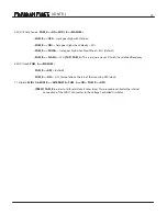
42. Contour: Onset Panel Control
43. Contour: Sustain Panel Control
44. Contour: Decay Panel Control
45. Contour: Activity Window <green>
46. Contour: Vari-Response
47. Contour: Decay Time CV INput
48. Contour: End of ONset (EON) Activity Window <yellow>
49. Contour: Gate INput
50. Contour: End of ONset (EON) OUTput
51. Contour: CV OUTput
52. Balance: CHannel 1 Signal INput
53. Balance: CV INput
54. Balance: Combo Pot
55. Dynamics: Combo Pot
56. Dynamics: Activity Window <orange>
57. Headphone/Line OUTput: Level Control
58. Headphone/Line OUTput: TRS Stereo Audio Signal, 3Vpp
59. Dynamics CV INput
60. Dynamics OUTput: Modular level Audio Signal, 10vpp
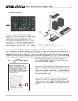
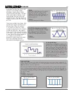
What is an oscillator?
An oscillator outputs repeating voltage in the
range of -5v to +5v. The core of the 0-Coast
generates voltage that ramps up in a straight line
and then back down, creating a triangle shape.
The other waveform outputs are created by using
circuitry to mold the Triangle into other shapes,
each of which has a unique sound. The frequency
of oscillation determines the pitch: the higher the
frequency, the higher the pitch.
An oscillator is ALWAYS oscillating: the only
thing that stops it is powering down the
system.
+5V
-5V
Figure 39:
0-Coast: Simultaneous Waveform Outputs
+5V
-5V
Time
Time
Figure 38:
Patch Instruction: SQUARE OUT to BALANCE Ext. IN
Содержание 0-Coast
Страница 1: ...5 19 16 REV 7 v 1 16...
Страница 9: ...8 Figure 8 Default Sound Figure 9 Drone...


