


Modulation with Slope
In addition to the MULTIPLY Panel Control the SLOPE circuit could act as a “ghost
hand” to adjust the MULTIPLY Panel Control in your absence. A gold wire indicates
the SLOPE circuit is able to modulate the MULTIPLY circuit via a Normalization at the
MULTIPLY CV IN Jack. This means that with nothing patched to the MULTIPLY CV IN
Jack, the SLOPE Signal OUT will pass through the MULTIPLY CV IN Jack to the
MULTIPLY CV Attenuvertor and from there it goes on to modulate the MULTIPLY
circuit. One way to hear this is to set the SLOPE circuit to CYCLE by
[PRESSING]
the
CYCLE Button until it
<lights white>
. Adjusting the RISE, FALL, Vari-Response, and
MULTIPLY CV Attenuator and Panel Controls alters the way the timbre of the
0-COAST is modulated. The CV Attenuvertor is capable of adding and subtracting
from the Panel Control with the “OFF” point being at 12 o’ Clock. The SLOPE and
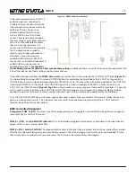
MULTIPLY Activity Windows
[light]
to indicate the activity
(
Figure 42
)
. Before you
read on to learn the functionality of these controls, take a moment to experiment
and search for unfound sounds.
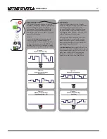
The SLOPE may be TRIGgered or set to Self-CYCLE. Triggering creates a single cycle: a single shot function starting at 0V,
traveling up to 8V and then immediately beginning the descent back to down to 0V. We will learn more about TRIGgered
SLOPEs in the second half of this manual. Begin by setting SLOPE Self-CYCLE ON. This creates a continuous Function starting
at 0V, traveling up to 8V, and then immediately beginning the descent back to 0V, repeating this behavior until the the CYCLE
Button is
[PRESSED]
again to disengage Self-CYCLE. This type of Function is often called a Low Frequency Oscillator or LFO:
an important element of both EAST and WEST Coast synthesis techniques.
RISE sets the amount of time the circuit takes to travel up to the maximum voltage level. Setting RISE to be more clockwise
increases the time it takes for the SLOPE to reach the maximum level, thus slowing down the LFO.
FALL sets the amount of time the circuit takes to travel
back down to the minimum voltage level. Setting FALL to
be more clockwise increases the time it takes to for the
SLOPE to reach the minimum level, again, slowing down
the LFO.
These two controls are also useful for determining the
shape of the LFO. For example, a fast RISE Time with a
slow FALL Time results in a Saw shape. If RISE and FALL
are set to similar times, it results in a Triangle shape.
(Figure 43).
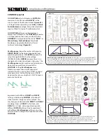
Vari-Response shapes these rates of change (i.e. RISE/
FALL) to be Logarithmic, Linear, or Exponential (
Figure
44
). With LOG response, the rate of change DECREASES as the voltage INCREASES. With EXPO response, the rate of change
INCREASES as the voltage INCREASES. LINEAR response has no change in rate as the voltage changes. The Vari-Response
control is also useful to increase or decrease the overall time or speed of the LFO. Setting Vari-Response more clockwise to
be more Exponential increases the LFO rate, while setting it to be more linear decreases the LFO rate.
22
Figure 43 RISE and FALL Times; Linear Response
Figure 42: MULTIPLY and SLOPE LED Activity
LINEAR FALL
EXPONENTIAL FALL
Figure 44: Vari-RESPONSE Settings
Note: This assumes the Rise Panel Control is set Full CCW so it is not affected. Also, this assumes FALL is set to around10 o’clock.
LOGARITHMIC FALL
Содержание 0-Coast
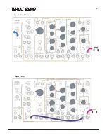
Страница 1: ...5 19 16 REV 7 v 1 16...
Страница 9: ...8 Figure 8 Default Sound Figure 9 Drone...


