17
BE 58-602 Pulsar
®
Model R96 Radar Transmitter
2.4.1.5 Standpipes and Stillwells
The PULSAR Model R96 can be mounted in a standpipe
or stillwell but certain items must be considered:
• Metal stillwells only: Sizes 100–200 mm (4–8"). (Beyond
200 mm (8"), effects are negligible.)
• Diameter must be consistent throughout length; no reducers.
• Use only horn antennas sized to pipe inside diameter (ID);
100–150 mm (4–6"); 200 mm (8") pipe can use a 6" horn.
• Stillwell length must cover complete range of measurement
(i.e., liquid must be in stillwell).
• Welds should be smooth.
• Vents: holes < 13 mm (0.5") diameter, slots < 13 mm (0.5")
width.
• If an isolation valve is used, it must be a full port ball valve
with an I.D. equal to the pipe diameter.
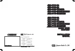
• Bridles/Bypass Installations: The launcher (index mark)
should be rotated 90° from process connections.
• Configuration must include an entry for the STILWELL I.D
parameter. See Section 2.6.5.
• There will be some increased dielectric sensitivity; system
gain will be reduced when STILWELL ID > 0.
2.4.2 Installing the Transmitter
• Remove the protective plastic cap from the top of antenna.
Store the cap in a safe place in case the transmitter has to be
removed later.
• Carefully place the transmitter on the antenna.
• Rotate the transmitter to face the most convenient direction
for wiring, configuration and viewing. Do not tighten the
universal connector (large hex nut) nor the set screw on the
housing base. The transmitter launcher must be oriented
properly for optimal performance.
• Do not place insulating material around any part of the
radar transmitter including the antenna flange.
2.4.2.1 Orientation
The PULSAR Model R96 transmitter utilizes a linearly
polarized, microwave beam that can be rotated to improve
its performance. Proper orientation can minimize unwanted
target reflections, decrease sidewall reflections (multipath)
and maximize direct reflections from the liquid surface. The
index mark located on the side of the launcher is oriented in
the same direction as the polarization.
The index mark is also present for reference(1 dot: GP/IS or
2 dots: XP). The launcher is considered to be at 0° when
the index mark is closest to the tank wall.
(See figures at left.)
45
°
Polarization Pattern
PULSAR Model R96 Mounted in
Stillwell (Bridle)
Set Screw
Universal
Connector
Index Mark
1 dot: GP/IS
2 dots: XP
Index
Mark
index
mark