background image

__0_ _0000 0 _____0___0_ 0 0 0 0_ _0_0 0__ 0_0___ 0_ _0_ _0__0_ ____0___ ___ _ 0 _______0________

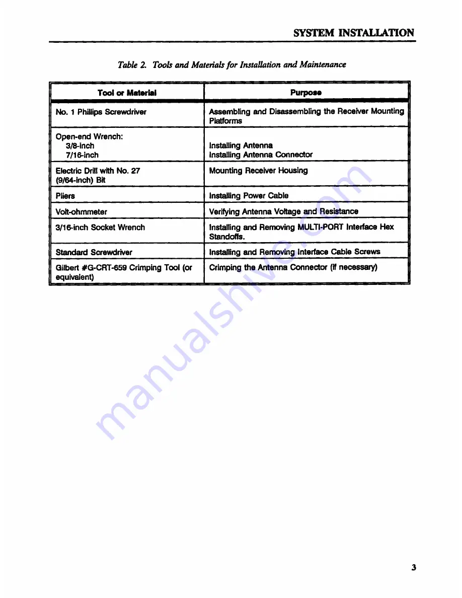
r__ _. r__ __ M_ten__ _or I_r_Y_rion D_ M_intenDnc_

_^^__ ^__ _____^__ m_^____ ^__^_^^' ^'^ _^' ______ ^^^ ^ ^ ^ _^^^_
hto. 1 Phillips S48wdiNer _ambling 8nd ___embling th_ Re_N_r Mounting _
P_orms
p8n-end wr8nch:
3__in ch l ns_ling Anten na
7J1 _tn_h Installin9 Ant0n__ Conn0_Y _
Ele_ri_ Drtll Mh No. 27 Mounting Re_her Houstng
(9J_-in_h) B_ _
P_'_rs In_ling Pow_r C_l8 _
V__h_et8r V8r_in9 Antenna Vo_9e and Res__ _
3/1_-_nch m__t wr8nch _n6tal_._ng _d Re_v'_ng muLTl-__ lnt8__ H_ __,
S_ndotM. _
Stand8d S4_wd_N_r In_ling _d R8rnoving Int8___ C_l_ Sy8_ _
_ilbe_ dG-CRT-859 Crimping T_l (or Crtmping m_ _t_nna Conn__Dr (_ n8_) _
8q u N_e nt) ,,

Содержание MX 9012R

Страница 1: ...DGPS 12 CHANNEL INSTALLATION AND SERVICE MANUAL Prepared by Magnavox Electronic Systems Company West Coast Division 2829 Maricopa Street Torrance Califomia 90503...

Страница 2: ...West Coast Division Magnavox reserves the right to make changes to its products and specitications without notice Printed in the United States of America...

Страница 3: ...like more in depth information about Magnavox DGPS products refer to the referenced documents below Thank you IMPORTANT NOTICE GPS satellites still remain in the trial stages Moreover the stated polic...

Страница 4: ...a Safe Physical Environment 10 Allowing for Proper Distances 10 Allowing Access to Rear Panel 10 Power and Memory Backup Q 11 Procedure 12 Connecting the Receiver to Extemal Equipment 14 Standard Por...

Страница 5: ...9 6 Rear Panel of the DGPS 12 Channel Receiver 11 7 Installation Template 12 8 MULTI PORT Interface Connector Pin Assignments 15 9 Magnavox Receiver to PC Interface Connector and Cables 16 10 Receive...

Страница 6: ...e Assembly MX 9012R 900555 806 1 Volute Antenna Assembly w 15m Cable MX 9212 MX 9012R 819766 801 1 Low Profile Antenna Assembly w gnd Plane 723008 801 1 Mx 9112 1 15 Meter RG 6 Cable MX 9112 567271 80...

Страница 7: ...installation Antenna proper length and routing of cable safe distance from high power antennas and transmitters appropriate height and mounting surface providing a 360 degree view of horizon Receiver...

Страница 8: ...Mounting _ P_orms p8n end wr8nch 3__in ch l ns_ling Anten na 7J1 _tn_h Installin9 Ant0n__ Conn0_Y _ Ele_ri_ Drtll Mh No 27 Mounting Re_her Houstng 9J_ in_h B_ _ P_ _rs In_ling Pow_r C_l8 _ V__h_et8r V...

Страница 9: ...t 1 meter above any large metallic horizontal surface Note Small diameter obstructions such as masts booms and kingpins do not seriously degrade signal reception but such objects must not eclipse more...

Страница 10: ......

Страница 11: ...DIA PIPE OR RAIL 130 MM 5 16 IN 28 MM 1 1 IN MAXIMUM as uu l 1 71 IN 82 5 MM 1 T 3 25 IN T Figure 2 Navigator Vertical Horizontal Antenna Mounting and Dimensions 3 Route the cable as directly as you...

Страница 12: ...attach it You should measure about 2 K ohms g 10 between the antenna connector and ground shield GQIPIIB HG 4 p 4 U 0 25 2 M8 P A E I 8 CABLE OENTE OONHXZTOR mo msuumou mm IUTE ALLDIMBIBIIJS III Il I...

Страница 13: ......

Страница 14: ......

Страница 15: ...t P N B19807 801 Allowing for Progr Distances Give some thought to the location of the unit You may wish to visually monitor the three status indicators red yellow and green LEDs willed traffic lights...

Страница 16: ...ntrol the unit power remotely you must have the power switch set to the REMOTE position and be able to apply 5 Vdc to a relay switch in the unit Remote power is controlled through the DB 25P connector...

Страница 17: ......

Страница 18: ...to reduce interference in the Navigator and other equipments Connect the unit power cable to a dc power source CAUTION Be sure you connect the positive lead ofthe power input cable identified by the w...

Страница 19: ...a stand alone unit or as a component in an integrated system Standard Port Uses Ports 1 and 3 are RS 232 ports ports 2 and 4 are RS 422 ports Port 1 is fixed as the Control Port All ports are default...

Страница 20: ...2 0u1 I u1 I RS422 I I PORT 2 INPUT _ F RT 2 14 I I PORT 2 INPUT 8 I I PORT 3 OUTPUT I I RS 232 S I I PORT 3 INPUT PORT 3 I I PORT 3 GROUND 5 I I PORT 4 OU I PUT 7 I Pom 4 OUTPUT I gs 422 4 I I Pom 4...

Страница 21: ...__ _ EIIIII ummm mmam z T a Ill nmuvnmnaq rumen s 0H I 4l 9 ________ _ n m __ _ PGTATD 1 ________ O __ npw_ mqp p 4 M 4 ________ 7 4 EB hATA l _IH ________ EGIEGF H w EEE EIUIEOIH 8 28 umw PETIOUT A r...

Страница 22: ...a table of satellite rise time predictions The receiver is able to navigate or calculate corrections while making these calculations Your receiver will probably have already acquired an almanac You ca...

Страница 23: ...corrections Yellow light tums off GREEN Magnavox receiver is navigating or computing corrections No other lights are on During normal operation the receiver cycles between yellow no tracking flashing...

Страница 24: ......

Страница 25: ...EDs referred to as trafiic lights The rear panel is attached to the chassis by one Phillips screw and parts on the two cards namely the Antenna connector on the RF power supply card and the MULTI PORT...

Страница 26: ...ounting base The screws sit in recesses in the mounting platforms at the sides of the unit 5 Separate the two halves of the outer casing 2 Be careful I he unit falls apart as you separate the two halv...

Страница 27: ...4 2 Clam Shell Housing Case Ref 2 3 Circuit Card Assembly Screw Ref 2 4 RF Power Supply Circuit 819822 801 802 1 5 Antenna Input Connector Ref 1 6 Chassis Ret 1 7 Hex Standoff Ref 1 set 8 Power Cable...

Страница 28: ...shield 10 into position on the replacement RF power supply card 4 2 Replace the nut and washer on the Antenna input connector 5 3 Replace the phillips head screw throu the rear anel 9 P 4 Verify that...

Страница 29: ...card center Tighten only until snug Don t over tighten 11 Replace the two hex standoffs 7 on the MULTI PORT Interface Connector Tighten only until snug Don t over tighten 12 Set down the receiver and...

Страница 30: ...ing a cold start Neither the warm start nor the tepid start will erase the almanac PROCEDURE Follow the initialization steps in the Magnavox DGPS 12 Channel Operator s Manual to execute the Magnavox C...

Страница 31: ...an aid you in identifying common problems Use Table 6 to identify common problems and remedies Table 6 Troubleshooting Table Status Indicators Rad Y now Probable Cause Recommended e _ _ _ _ Em _ _ _r...

Страница 32: ...ons of the circuit card assemblies and analog section of the RF power supply CCA REMOTE CONTROL SOURCES IBM PC with control software provisions for remote ON OFF oontrol SIGNAL INPUT A __ RECEIVER TYP...

Страница 33: ...tatus navigation data time DATA FORMATS NMEA 0183 proprietary RTCM 104 ASCII I PHYSICAL DATA RECEIVER DIMENSIONS Height 45 millimeters 1 8 inches Width 138 millimeters 5 4 inches Depth 177 millimeters...

Страница 34: ...Receiver 40 to 85 C 40 to 185 F l i Antenna 40 to 85 C 40 to 185 F I i Hurvnomr l Receiver 95 i Antenna 100 r A Y v iiv m V TTTTTJ e i nowzn DATA 4 AA AAAAA AAA AA A AAAAAAA A A AAA A A A AAAAAA i POW...

Страница 35: ...e title and identification number of this manual Magnavox DGPS 12 Channel Installation and Service Manual R 7218 and include your name address and telephone number We look forward to Ending out how we...

Страница 36: ...ou like All comments and suggestions become the property of Magnavox Do not use this form to request purchases maintenance assistance or additional publications Please contact your Magnavox marketing...

Страница 37: ...Paste Stamp Here MAGNAVOX ELECTRONIC SYSTEMS COMPANY WEST COAST DIVISION 2829 Maricopa Street Torrance CA 90503 USA Attn Navigation Positioning Dept 775 Technical Writing Supervisor...

Страница 38: ...is connected to the raw data port 2 LAT DON Do you have high power transmitting equipment such as radar or Indicate GDOP SSB radios What are the signal strengths of satellites under track HDOP and VDO...

Страница 39: ...Paste Stamp Here Magnavox Electronic Systems Company West Coast Division 2829 Maricopa Street Torrance CA 90503 USA Attn Navigation Positioning Dept 775 Technical Writing Supervisor...

Страница 40: ...N OF YOUR NEAREST AUTHORIZED SERVICE REPRESENTATIVE MAGNAVOX ELECTRONIC SYSTEMS COMPANY WEST COAST DIVISION 2829 Maricopa Street Torrance CA 90503 U S A A I I N MSSD FIELD SERVICE MANAGER PHONE 310 32...

Отзывы: