SYSTEM INSTALLATION
CONNECI`ING THE RECEIVER TO EXTERNAL EQUIPMENT
External equipment connects to the MULTI-PORT Interface connector on the rear panel of the
receiver unit (see Figure 6). The interface consists of four Input/Output (I/O) serial ports; two RS-
232 ports and two RS-422 ports. IBM compatible (DOS-based) software controls the
communications. Figure 6 shows you the MULTI-PORT Interface connector pin assignments. If
you are logging data with a personal computer (PC) on one of the two RS-422 ports (2 and 4), you
will need the optional RS-422 to RS-232 data converter kit, P/N 741692-804. You determine the
exact use of the individual I/O ports by your needs and choice of associated equipment. You may,
for example, use the Magnavox Navigator to navigate as a stand-alone unit or as a component in an
integrated system.
Standard Port Uses
Ports 1 and 3 are RS-232 ports; ports 2 and 4 are RS-422 ports. Port 1 is fixed as the Control Port.
All ports are defaulted to 9600 baud. Here are their standard functions:
• Port 1 · RS-232, Operational control and data messages (9600 baud default)
[input/output]
• Port 2 - RS-422, Measurement (Raw data) [output]
• Port 3 - RS-232, DGPS Corrections I/O (MX-SOR) [input for navigators, output for
reference stations]
• Port 4 - RS-422, Equipment/NMEA [input/output]
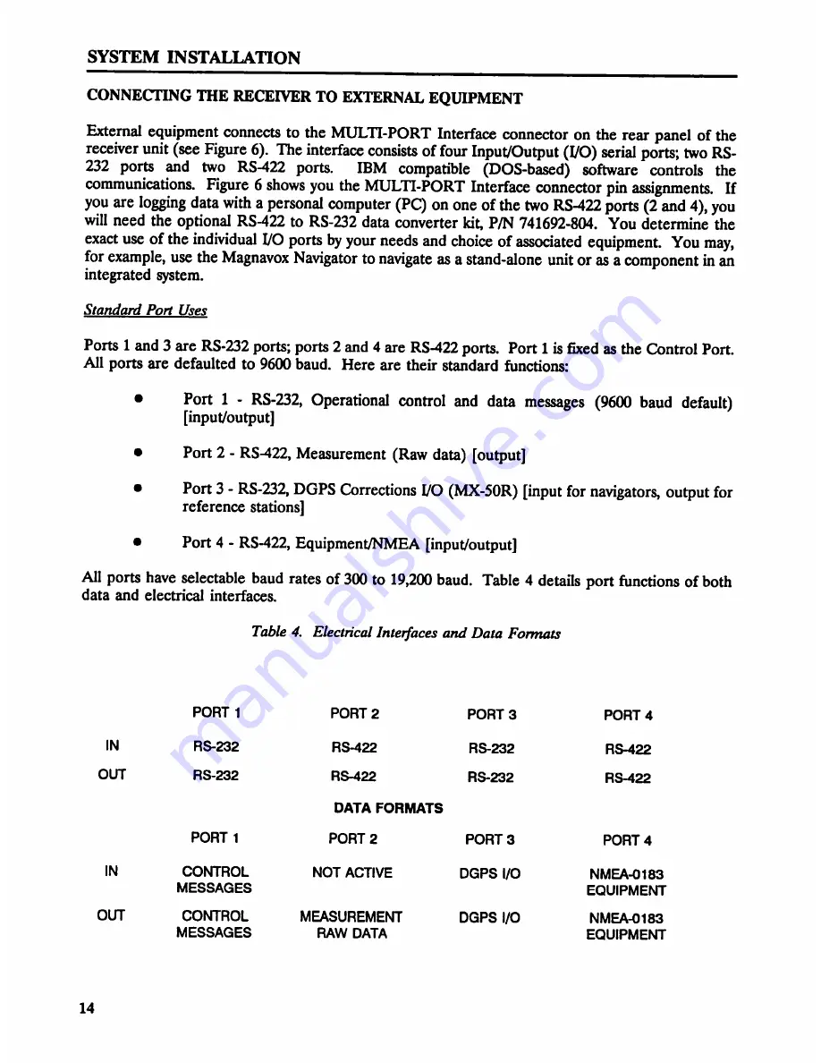
All ports have selectable baud rates of 300 to 19,200 baud. Table 4 details port functions of both
data and electrical interfaces.
Table 4. Electrical Interfaces and Data Formats
PORT 1 PORT 2 PORT 3 PORT 4
IN RS-232 RS-422 RS-232 RS-422
OUT RS-232 RS-422 RS-232 RS-422
DATA FORMATS
PORT 1 PORT 2 PORT 3 PORT 4
IN CONTROL NOT ACTIVE DGPS I/O NMEA-0183
MESSAGES EQUIPMENT
OUT CONTROL MEASUREMENT DGPS I/O NMEA-0183
MESSAGES RAW DATA EQUIPMENT
14


