


You can give the instrument an easy-to-remember
nickname for remote APP identification.
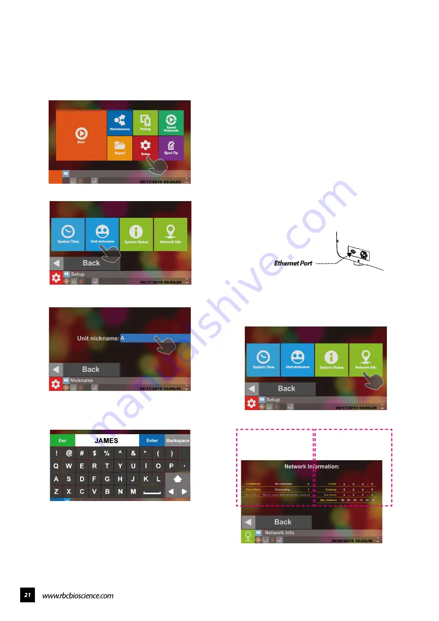
Select Setup Button
Select Unit Nickname
Select the blue square as shown in the figure
above.
Enter the name you want to give to the instrument
and then press Enter to finish adding or changing
the name.
The network connection is used for the remote
monitoring APP and LIMS data transmission.
To set the remote monitoring app, you need
to first to check up with your IT staff that your
network environment has DHCP service and can
connect to the Internet and open the firewall 8083
(out), 1883 (out), 8883 (out), 80 (out) , 443 (out)
port.
When using LIMS data transfer, you need to
first establish a 21 (in) connection with the IT
staff to determine the firewall of your PC. When
transmitting as a LIMS data, we operate on the
internal network.
After setting the network environment to meet
the above rules, please insert the network route
into the network port of the instrument and boot
it.
After the connection is made, the network
will automatically assign one IP location to
the instrument. We must make sure that the
instrument is assigned to one IP
Press Setup Button
Select Network Info
Please confirm the displayed TCP/IP location and
DHCP server. The same network segment is sent
to complete the network settings.
━ Set the Instrument Nickname
━ Network Connection Settings
Remote Monitoring APP
Server Connection Status
Regional Network
Connection Status
Содержание Plus II
Страница 1: ......
Страница 5: ...Specification Operating Parameters Operating Environment Applications...
Страница 6: ...IQ OQ PQDocuments IQDocuments...
Страница 7: ...OQ Documents...
Страница 8: ...PQ Documents...
Страница 9: ......
Страница 10: ...Accessories Installation 1 2 3 4 5 7 6 8 9 10 11 BeforeInstallation...
Страница 11: ...System Overview...
Страница 14: ...Installation...
Страница 15: ......
Страница 33: ...Replace Fuse Please use the specified type of fuse tominimizetheriskofburning...
Страница 35: ......
Страница 36: ...Disassemblethehousing 1 Loosen the two bottom screws to about 3mm...
Страница 37: ...2 Remove the remaining eight screws and take off the lid...
Страница 40: ...Axisdirections V axisdirection Y axisdirection M axisdirection V axisdirection X axisdirection...
Страница 42: ...ReplaceLEDlight 1 Remove the LED light from the top panel 2 Install a new LED light and hold it with cable ties...
Страница 49: ...Replace the sensor ofX axis 1 Remove the wire connected with the sensor 2 Remove the two screws on the sensor...
Страница 59: ...Replace Solid StateRelay SSR 1 Remove the two screws on SSR Remove the SSR and replace with a new one...
Страница 60: ...Electrical controlandengineeringsoftware...
Страница 61: ...Main board configuration...
Страница 66: ...10 Go to System Status and check the PLC version...
Страница 69: ...5 Go to System Status and check the HMI version...
Страница 72: ...6 Tap Confirmation when the program update is complete 7 Go to System Status and check the program version...
Страница 78: ......
Страница 79: ......
Страница 80: ......


