


Touch Panel and User Interface
MagCore® Plus II provides 7-inches full-color touch panel and easy-to-use user interface.
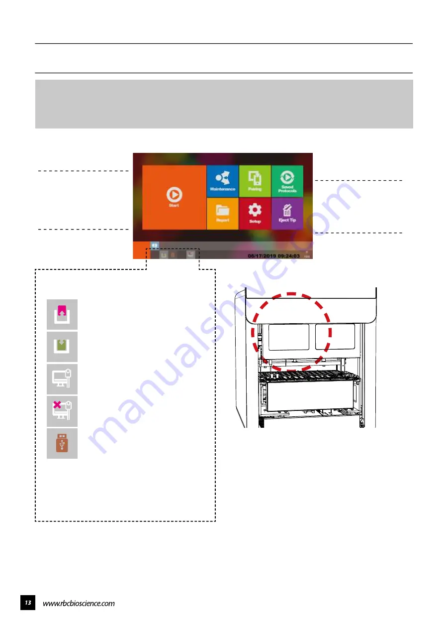
Operator only needs to pay attention to the panel to know the current status, ending time and
test report of the machine. The figure below shows the function list of the operation screen and
the description of the status icons.
Start
Report
Setup
Saved Protocols
Maintenance
Eject Tip
Execute Extraction
Execute quick run with
selection of pre-saved
protocols
System Maintenance
Functions
Overview of the latest
runs with barcodes
System Settings
Status Column Icons
Panel Board Lighting
Front Door is Open
Front Door is Closed
Machine Connected to Network
Machine is not Connected to
Network
USB Flash Drive Plugged In
* Format USB Flash Drive to FAT32
The Panel will light up the following lights when the
instrument is in operation:
Blue Light: The Instrument is on Stand-by
Green Light: The Instrument is in Operation
Red Light: The Instrument Gives a Warning Alert
Содержание Plus II
Страница 1: ......
Страница 5: ...Specification Operating Parameters Operating Environment Applications...
Страница 6: ...IQ OQ PQDocuments IQDocuments...
Страница 7: ...OQ Documents...
Страница 8: ...PQ Documents...
Страница 9: ......
Страница 10: ...Accessories Installation 1 2 3 4 5 7 6 8 9 10 11 BeforeInstallation...
Страница 11: ...System Overview...
Страница 14: ...Installation...
Страница 15: ......
Страница 33: ...Replace Fuse Please use the specified type of fuse tominimizetheriskofburning...
Страница 35: ......
Страница 36: ...Disassemblethehousing 1 Loosen the two bottom screws to about 3mm...
Страница 37: ...2 Remove the remaining eight screws and take off the lid...
Страница 40: ...Axisdirections V axisdirection Y axisdirection M axisdirection V axisdirection X axisdirection...
Страница 42: ...ReplaceLEDlight 1 Remove the LED light from the top panel 2 Install a new LED light and hold it with cable ties...
Страница 49: ...Replace the sensor ofX axis 1 Remove the wire connected with the sensor 2 Remove the two screws on the sensor...
Страница 59: ...Replace Solid StateRelay SSR 1 Remove the two screws on SSR Remove the SSR and replace with a new one...
Страница 60: ...Electrical controlandengineeringsoftware...
Страница 61: ...Main board configuration...
Страница 66: ...10 Go to System Status and check the PLC version...
Страница 69: ...5 Go to System Status and check the HMI version...
Страница 72: ...6 Tap Confirmation when the program update is complete 7 Go to System Status and check the program version...
Страница 78: ......
Страница 79: ......
Страница 80: ......


