MSP40 / MSP50
5-2-55, Minamitsumori, Nishinari-ku, Osaka 557-0063 JAPAN
Phone: +81(6)6659-8201 Fax: +81(6)6659-8510 E-mail: [email protected]
EM-4883 P. 8 / 18
9. COMBINATION WITH VALVE
■
OPERATION DISTANCE WHEN COMBINED WITH VALVE
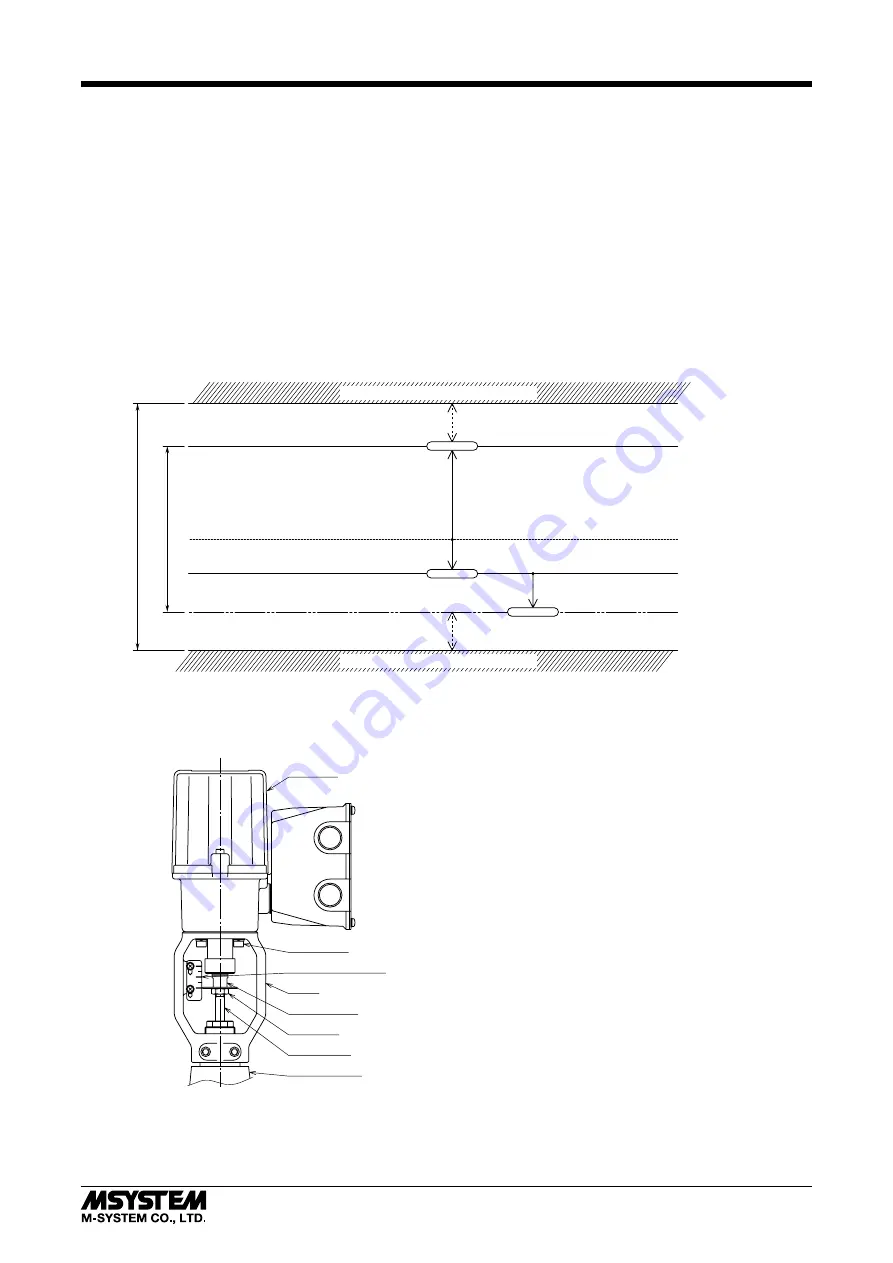
When setting the upper-stop position and the lower-stop position, it is preferable that the operation distance becomes 80%
or less with respect to the maximum stroke of the actuator.
That is, when the valve is closed at the lower-end side of the actuator, if the maximum stroke is 20 mm and the lower-stop
position is set at the 20.0 mm position, there will be no margin for the actuator to further go down to close the valve when
valve leakage occurs. In such a case, Auto-setup may not be successfully completed.
In order to avoid such a situation, select an appropriate combination of an actuator and a valve to secure an enough opera-
tion distance. In the example below, the maximum stroke is 20 mm and thus the preferable operation distance is 16.0 mm.
Set so that the distance between the upper-stop position and the lower-stop position are within the operation distance of
16.0 mm.
■
EXAMPLE OF PROPER OPERATION DISTANCE
When connecting the output stem of the actuator with the valve stem, determine their mounting position so that a proper
operation distance can be secured.
Max. Stroke: 20.0mm
16mm max. (rough indication)
Upper Stop Position
Lower Stop Position
Valve seat surface (seating position)
Max. Spring contraction
when leakage occurs
Stop
Stop
set by Auto-setup
Spring contraction: approx. 0.1 mm
Upper-End of Max. Stroke
Lower-End of Max. Stroke
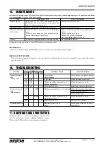
• Example of MSP Mounted to Valve
Actuator
Bolts (M5)
Position Indicator
Yoke
Output stem
Lock nut
Valve stem
Valve bonnet


