background image

Reference Manual D AA 5320 Version 2.0


Page 15  


Installation 


Caution 

The CardModule is shipped in a 

protective anti-static bag. Please take 
suitable precautions to avoid static 

discharge onto any part of the PCB or 

components when handling module or 
serious damage could result. 


Each Card Module is supplied with a rear 
connection panel and two mounting screws. 

Please follow the following procedure for 

installation of the card module into the Series 5000 
Card Frame. 


a)


Select a slot in the card frame where the 
CardModule will be located 

b)


Remove the blank connection panel from the 

rear of the rack (if fitted) 

c)


Install the rear connection panel using the 

screws supplied. Do not tighten the screws fully 

d)


Slide the card module into the card frame and 
carefully check the CardModule easily 

connects to the rear connection plate. The 
card should fit easily and should not require 

excessive force to insert, if you feel any 

resistance, there could be something wrong 
with the rear connection panel location. Do not 

try and force the connection. Remove the rear 

connection panel and check alignment with 
the CardModule. 

e)


Insert and remove the CardModule a few times 

to ensure correct alignment and then tighten 
the two screws to secure the rear connection 

plate 


Содержание D AA 5320 D

Страница 1: ...Series 5000 Reference Manual D AA 5320 D D AA 5320 S Analog Audio Distribution Amplifier CardModule Version 2 0 LYNX Technik AG Brunnenweg 3 D 64331 Weiterstadt Germany www lynx technik com ...

Страница 2: ...ritten permission of LYNX Technik AG LYNX Technik AG may have patents patent applications trademarks copyrights or other intellectual property rights covering the subject matter in this document Except as expressly written by LYNX Technik AG the furnishing of this document does not give you any license to patents trademarks copyrights or other intellectual property of LYNX Technik AG or any of its...

Страница 3: ...rranty shall not apply to any defect failure or damage caused by improper use or improper or inadequate maintenance and care LYNX Technik shall not be obligated to furnish service under this warranty a to repair damage resulting from attempts by personnel other than LYNX Technik representatives to install repair or service the product b to repair damage resulting from improper use or connection to...

Страница 4: ...perated in a commercial environment This equipment generates uses and can radiate radio frequency energy and if not installed and used in accordance with the instruction manual may cause harmful interference to radio communications Operation of this equipment in a residential area is likely to cause harmful interference in which case the user will be required to correct the interference at his own...

Страница 5: ...S 13 Audio Connections balanced 13 Audio Connections un balanced 14 Installation 15 Settings and Control 16 Switch Settings 17 Factory Preset Condition 17 Adjustment Procedures 18 Set Stereo Mono Mode 19 Set Unity Gain using gang mode 20 Set Unity Gain Individual channels 21 Set Stereo Gain Levels Using Gang Mode 22 Set Stereo Gain Levels Individually 23 Set Mono Gain Level 24 Auto Store 24 Alarm ...

Страница 6: ...Reference Manual D AA 5320 Version 2 0 Page 6 This page is intentionally left blank ...

Страница 7: ...lication or a 1 to 8 mono application The module has adjustable gain and signal presence detection is provided for each channel Local presets adjustments and alarms are provided on each module as well as optional remote control status reporting and SNMP error reporting using the LYNX central control system The D AA 5320 is part of the 5000 series of CardModules which offer high quality modularity ...

Страница 8: ...ection panel The rear connection panel utilizes Sub D connectors D AA 5320 D or Weco type connectors D AA 5320 S for the audio input and outputs Please refer the connections section of this manual for wiring details for the connectors Gain Adjustment Gain Adjustment Presence Detection Micro Controller Presence Detection OUT Left 1 OUT Left 2 OUT Left 3 OUT Left 4 OUT Right 1 OUT Right 2 OUT Right ...

Страница 9: ...Reference Manual D AA 5320 Version 2 0 Page 9 Figure 2 Module Layout ...

Страница 10: ...Reference Manual D AA 5320 Version 2 0 Page 10 Caution Use static precautions when handling the PCB Static discharge could result in serious damage to the module ...

Страница 11: ...audio signals twisted pair suitable for balanced audio signals Audio Output Connections balanced SubD 25 pin female connector TASCAM pinout Figure 3 Audio output connection detail Pin Number Connection Pin Number Connection 1 Left 1 14 Left 1 2 GND Left 1 15 Right 1 3 Right 1 16 GND Right 1 4 Left 2 17 Left 2 5 GND Left 2 18 Right 2 6 Right 2 19 GND Right 2 7 Left 3 20 Left 3 8 GND Left 3 21 Right...

Страница 12: ... balanced audio connections to the module Figure 4 Audio wiring detail NOTE When used in this manor certain technical specifications of the module cannot be maintained Twisted pair blanced audio Balanced Pin Identification Wiring for balanced audio Wiring for un balanced audio Screen GND Signal Screen Input output Input output GND Pin Number Connection Pin Number Connection 1 9 2 10 3 11 4 LEFT IN...

Страница 13: ...n accordance with the table below Please use high quality screened cable to prevent the introduction of noise and interference to the audio signals twisted pair suitable for balanced audio signals Audio Connections balanced Weco 3 pin connector Weco male connector on module 1 2 3 1 2 3 Weco female connector Figure 5 Weco connection detail Pin Number Connection 1 Positive 2 GND 3 Negative ...

Страница 14: ...it is possible to make un balanced audio connections to the module Figure 6 Audio wiring detail NOTE When used in this manor certain technical specifications of the module cannot be maintained Twisted pair blanced audio Balanced Pin Identification Wiring for balanced audio Wiring for un balanced audio Screen GND Signal Screen Input output Input output GND ...

Страница 15: ...be located b Remove the blank connection panel from the rear of the rack if fitted c Install the rear connection panel using the screws supplied Do not tighten the screws fully d Slide the card module into the card frame and carefully check the CardModule easily connects to the rear connection plate The card should fit easily and should not require excessive force to insert if you feel any resista...

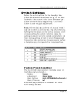
Страница 16: ...atically saved in non volatile internal memory Flash ram The module will always recall the settings used prior to power down The module local configuration and gain settings are performed using a 4 position dip switch and up down adjustment switch on the front edge of the module These controls are used to preset stereo or mono operation and set the required gain parameters within the module Please...

Страница 17: ...able the setting or adjustment of a certain parameter and then storing settings in flash memory Please read this section fully and review the procedures before attempting any changes to the module settings Factory Preset Condition The D AA 5320 is delivered with stored presets for the following functionality Mode Stereo Adjustment Gang Mode Gain Setting Unity OFF 0dB both channels Gain Channel Lef...

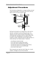
Страница 18: ...gs stored on internal flash ram To simplify the configuration and setting of the module a series of procedures has been defined to make setting the module easier These are Set Stereo Mono Mode Set Unity Gain using gang mode Set Unity Gain Individual channels Set Stereo Gain Levels Using gang mode Set Stereo Gain Levels Individually Set Mono Gain Level These procedures capture most things you would...

Страница 19: ...nced line outputs of this channel Use this procedure to select Stereo or Mono modes of operation 1 Set Switch 1 enable local adjustment to ON 2 Set Switch 2 stereo mono select to ON for Stereo or OFF for Mono 3 If 10 seconds pass with no further adjustments being made both channel status LEDS will flash yellow four times This confirms settings have been written into flash ram and stored 4 To preve...

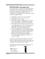
Страница 20: ...ls to unity gain 0dB The other channel will retain its previously stored relative offset if any 5 If 10 seconds pass with no further adjustments being made both channel status LEDS will flash yellow four times This confirms settings have been written into flash ram and stored 6 To prevent further accidental adjustment it is recommended to set Switch 1 enable local adjustment to OFF Gang mode of op...

Страница 21: ... once this will set unity gain in the selected channel 6 Select the other input channel and repeat steps 4 and 5 above 7 If 10 seconds pass with no further adjustments being made both channel status LEDS will flash yellow four times This confirms settings have been written into flash ram and stored 8 To prevent further accidental adjustment it is recommended to set Switch 1 enable local adjustment...

Страница 22: ...down will change the gain in a fast mode 6 If 10 seconds pass with no further adjustments being made both channel status LEDS will flash yellow four times This confirms settings have been written into flash ram and stored 7 To prevent further accidental adjustment it is recommended to set Switch 1 enable local adjustment to OFF To disable gang mode change the state of Switch 4 channel select once ...

Страница 23: ...Left 6 Push the DN or UP buttons to adjust gain level Each press changes the gain by 0 5dB holding the button down will change the gain in a fast mode 7 Select the other input channel and repeat steps 5 and 6 above 8 If 10 seconds pass with no further adjustments being made both channel status LEDS will flash yellow four times This confirms settings have been written into flash ram and stored 9 To...

Страница 24: ... a fast mode 5 If 10 seconds pass with no further adjustments being made both channel status LEDS will flash yellow four times This confirms settings have been written into flash ram and stored 6 To prevent further accidental adjustment it is recommended to set Switch 1 enable local adjustment to OFF When is mono mode the RIGHT channel status LED will go out Auto Store If no parameters are changed...

Страница 25: ...ed below Front Panel Alarm Indicator There is also a single alarm LED on the module figure2 which is designed for quick and easy indication of a problem condition and is visible through the front cover of the card frame Normal status is GREEN LED Color Indication Green Signal Present Yellow Set up aid Flashes during set up to indicate and confirm various operations Refer to set up procedures for d...

Страница 26: ...elected on the control system there is a locate button on the top of the GUI Locate Function in Control System When Locate is selected the status indicator on the GUI and the module LED s will flash yellow in the following continuous sequence 3 short flashes Pause 3 short flashes This uses the alarm LED located on the front of the module and in some cases any channel or status LED s that may be us...

Страница 27: ...ency Response 0 1dB 20Hz to 20KHz at 24dBu Distortion 0 002 20Hz to 20KHz at 24dBu S N ratio 98dB 20Hz to 20KHz A weighted Common Mode Rejection 90dB up to 20KHz Control Local settings dip switch Remote control of module configuration stereo mono and gain Status Monitoring Signal presence detection signal absence 30dBu for 5s Electrical Specifications Operating Voltage 12VDC Power Consumption 3 5 ...

Страница 28: ... Rack Frame empty with single power supply R FR 5011 Series 5000 Rack Frame empty with single power supply and front cover with integrated fans R PS 5010 Redundant power supply for the R FR 5010 Card Frame R CT 5030 Maste controllerwith TCP IP Interface for the R FR 5010 5011 Card Frame R CT 5020 Rack controller for the R FR 5010 5011 Card Frame R CT 5010 Rack Bus Extension for the R FR 5010 5011 ...

Страница 29: ...Amp Model Number D AA 5320 D Part Number 6 155 003 251 Sub Assemblies D AA 5320 Processing Board only BS 5004 Part Number 6 155 003 251 Rear Connection Panel for D AA 5320D MA 5010_B Part Number 6 155 008 245 D AA 5320 S CardModule complete Description Analog Audio D Amp Model Number D AA 5320 S Part Number 6 155 001 121 Sub Assemblies D AA 5320 Processing Board only BS 5004 Part Number 6 155 003 ...

Страница 30: ...distributor for assistance We offer a fixed cost service exchange program for defective Series 5000 CardModules out of Warranty Please contact your distributor or check our web site for details on this program More detailed information and product updates may be available on our web site www lynx technik com You will also find links to contact us directly for assistance ...

Страница 31: ... Technik can be contacted directly using the information below Address LYNX Technik AG Brunnenweg 3 D 64331 Weiterstadt Germany Website www lynx technik com E Mail info lynx technik com LYNX Technik manufactures a complete range of high quality modular products for broadcast and Professional markets please contact your local representative or visit our web site for more product information ...

Страница 32: ...Reference Manual D AA 5320 Version 2 0 Page 32 This page is intentionally left blank ...

Страница 33: ...Reference Manual D AA 5320 Version 2 0 Page 33 Notes ...

Отзывы: