background image

Maintenance

Finishing maintenance

23

© Lutz-Jesco GmbH 2018
Subject to technical changes.
180426

BA-40900-02-V01

Gas warning device 

EASYCON GW

Operating instructions

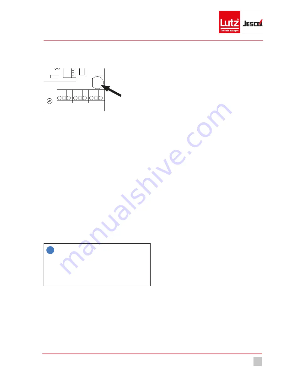
10.5  Replacing the fuse

Your device is fitted with an electrical fuse to protect against short circuits 
or over-voltage. You can change the fuse if it is defective.

8

1

9

2 3 4 5 6 7

10 11121314151617181920

2930313233343536

2122232425262728

37383940

41 42 43

44 45 46 47 48 49 50 51 52

USB

Fig. 13:  Position of the fuse

Precondition for action:

ü 

The voltage supply has been disconnected and protected against 
re-connection.

ü 

The housing is open.

Resources required:

Slotted screwdriver

New fuse: 5 x 20 mm, 3.15 A, 250 V (delay) 

Perform the following steps:

1. 

The fuse holder in the form of a bayonet catch is located at the bot-
tom right-hand side, above the clamps for PE, N and L with the mark-
ing “Fuse”. Use the slotted screwdriver to press the catch down-
wards and then turn it leftwards.

2. 

Remove the fuse.

3. 

Replace the fuse and fix it in place by turning the catch clockwise.

ü 

Fuse has been replaced.

10.6  Resetting the settings

i

The instructions differentiate between the internal factory set-
tings and the device configuration.

The factory settings contain the basic configuration of the de-
vice hardware and cannot be changed.

The configuration file (*.SET) contains the individual language 
configuration, the action of the sensors or the limit values. You 
can change, save and load the individual settings.

Reset to the factory settings

You can now reset the device to its factory settings. This deletes the con-
figuration. You must then either load a configuration file or perform the 
configuration manually.

Perform the following steps:

1. 

In the main menu, navigate to System > Service > Device.

2. 

Press “factory settings”.

3. 

Confirm with “Yes”.

The configuration will be deleted. You must proceed with the follow-
ing section.

ü 

All factory default settings will be reset.

Reset the configuration

The device configuration will be saved in *.SET files. A factory-set config-
uration file with standard settings is already present. You can change 
these or save your personal configuration in new files.

Recommendation: Leave the factory-set configuration file unchanged 
and save your personal configuration in a new file. Given problems with 
the configuration, this enables you to return to a functioning configuration 
quickly.

Perform the following steps:

1. 

In the main menu, navigate to System > Settings > Configuration.

2. 

Select an existing configuration file.

3. 

Click “Load” to confirm.

The device configuration returns to the saved state.

ü 

Load the old configuration.

10.7  Finishing maintenance

Perform the following steps:

1. 

Make a note of the date and scope of the maintenance performed.

2. 

In the “Service” menu, navigate to the “Service entry” tab. Enter your 
company name and notes about the maintenance. Activate the re-
minder function and enter a date for the next service. Confirm with 
the “Save” button .

Your service action has been saved in the logfiles.

3. 

To restart the system, proceed in accordance with the instructions in 
section 8 “Commissioning” on page 18.

ü 

Maintenance completed.

Internal fuse

Содержание EASYCON GW

Страница 1: ...Gases Systems Original operating instructions Lutz Jesco GmbH 2018 BA 40900 02 V01 Gas warning device EASYCON GW Operating instructions Read the operating manual The user is responsible for installati...

Страница 2: ......

Страница 3: ...5 Technical data 10 5 1 EASYCON GW 10 5 2 Sensors 10 6 Dimensions 11 6 1 Outside dimensions 11 6 2 Drillhole dimensions 11 7 Installation 12 7 1 Principles 12 7 2 Installation on the wall 12 7 3 Elect...

Страница 4: ...juries WARNING Refers to a potentially hazardous situation Failure to follow this instruction may lead to death or severe injuries CAUTION Refers to a potentially hazardous situation Failure to follow...

Страница 5: ...s through dangerous dosing media n danger to the environment caused by chlorine leaking from the system 2 3 Working in a safety conscious manner Besides the safety instructions specified in this opera...

Страница 6: ...to perform and about the dangers stemming from improper be haviour Trained persons have attended all trainings offered by the operator 2 4 4 Personnel tasks In the table below you can check what qual...

Страница 7: ...ed as non intended use This section is intended to allow you to detect possible misuse in advance and to avoid it Foreseeable misuse is assigned to the individual stages of the product lifetime 3 3 1...

Страница 8: ...ning device n Up to 4 sensors n Operating instructions 4 2 Design and function 4 2 1 Installation example Fig 1 Simple example installation of a chlorine gas room Position Description Position Descrip...

Страница 9: ...rine dioxide or ozone They can also measure the room temperature If the sensors notify too high a value the device will issue an alarm and the connected safety devices such as a signal bugle or sprink...

Страница 10: ...relay 250 V AC 10 A ohmic resistive load Analogue outputs 0 4 20 mA max load 500 ohms Interfaces Ethernet Modbus TCP IP Protection class IP 65 Ambient temperature 5 45 C Air humidity max 95 non conde...

Страница 11: ...changes 180426 BA 40900 02 V01 Gas warning device EASYCON GW Operating instructions 6 Dimensions All dimensions in millimetres mm 6 1 Outside dimensions Fig 4 Outside dimensions 6 2 Drillhole dimensi...

Страница 12: ...the rod 4 You can now open the device 3 Open the device and use the screws for wall mounting Ensure that the device is secured to the wall 4 Close the device again using the rod The device is fitted o...

Страница 13: ...ogue output 4 20 21 36 Digital inputs 1 8 Freely configurable 37 40 Ethernet connection 41 43 Horn relay Clamps 41 42 normal off Clamps 42 43 normal on 44 46 Connection supply voltage Protective earth...

Страница 14: ...5 Open the device housing and lead the cable into the inside of the housing through one of the cable screw connections on the under side of the housing 6 Connect the three coloured wires onto the inp...

Страница 15: ...underside of the device 3 Connect the signal technology used either to clamps 41 and 42 nor mal off or 42 and 43 normal on 4 Note You can adjust the action of the bugle relay in the output set tings...

Страница 16: ...d the device has been switched on Instruction 1 In the main menu navigate to System Outputs Test 4 You will now see all the outputs 2 Select the outputs that you would like to test 3 Press Start 4 The...

Страница 17: ...aximum cable length is 100 m n You must route separately as a bundle the different categories of cables e g power supply data lines and sensitive lines for measuring purposes In this connection cables...

Страница 18: ...eight digital inputs 8 2 1 1 Sensors The sensors must be configured individually in the device to enable pre cise and error free measurement of the gases You can perform various settings Perform the...

Страница 19: ...e exceeding of the limit value the alarm should be activated Configuration of the limit values completed 8 2 2 3 Digital output signals You can control the connected signal technology with digital out...

Страница 20: ...ent of the sensors are accessible here This level is required for device configuration and should only be operated by experienced users n 3 Level The service menu is accessible here This level is main...

Страница 21: ...values which are to be dis played in the trend 3 You can set the scaling of the individual trend display for every value individually Press on the Scaling tab select a sensor and define minimum and m...

Страница 22: ...the new sensor element It contains a short circuit connector which protects the sensor element against ageing during transport and storage 5 Remove the short circuit connector To do so pull on the gol...

Страница 23: ...t the device to its factory settings This deletes the con figuration You must then either load a configuration file or perform the configuration manually Perform the following steps 1 In the main menu...

Страница 24: ...ry is really empty To do so navigate to the menu System Information System values You can view the battery voltage under Battery If the voltage is under 3 V change the battery n Replace the battery Th...

Страница 25: ...mber 123456 will thus be transferred as Address 2000 0x3132 Address 2001 0x3334 Address 2002 0x3536 2003 x Status of the digital inputs Shows the logic of the clamps Not the configured software functi...

Страница 26: ...o type 2021 x Value HIGH WORD Two positions after decimal point 215 2 15 2022 x Value LOW WORD Two positions after decimal point 215 2 15 2024 x Temperature value One position after the decimal point...

Страница 27: ...alue 2 Sensor 1 sensor error Sensor 2 sensor error Sensor 3 sensor error Sensor 4 sensor error Sensor 1 temperature max Sensor 2 temperature max Sensor 3 temperature max Sensor 4 temperature max Senso...

Страница 28: ...mple con los requisitos sanitarios y de seguridad vigentes de las directivas de la U E citadas a continuaci n Esta declaraci n ser invalidad por cambios en el aparato realizados sin nuestro consentimi...

Страница 29: ...anty claim Sender Company Phone Date Address Contact person Manufacturer order no Date of delivery Device type Serial number Nominal capacity nominal pressure Description of fault Service conditions o...

Страница 30: ...the sensor 14 Connecting the signal technology 15 Installation example 8 Installation on the wall 12 Intended purpose 7 Intended use 7 Internal fuse 23 M Maintenance 22 Maintenance intervals 22 N Not...

Страница 31: ...31 Lutz Jesco GmbH 2018 Subject to technical changes 180426 BA 40900 02 V01 Gas warning device EASYCON GW Operating instructions...

Страница 32: ......

Отзывы: