9
luminancebrands.com
Please contact 1-800-777-4440 for further assistance
Model No.: RCK55
Receiver Installation (Continued)
3.6
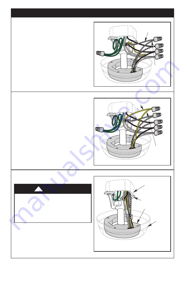
8. Cut off the black shrink tubing, if present, on the
Receiver Blue Wire and strip back insulation 1/2”
from the end of the Wire.
9. Securely connect the Receiver Blue Wire
(BOTTOM LIGHT) to the Fan Blue Wire
using the Wire Connector (supplied in parts bag)
(Figure 19).
NOTE: If your ceiling fan does NOT have a downlight,
cap the blue receiver wire using a wire connector
(supplied).
FAN BLUE WIRE
RECEIVER
BLUE WIRE
(BOTTOM LIGHT)
Figure 19
FAN YELLOW WIRE
RECEIVER
YELLOW WIRE
(UPPER LIGHT)
Figure 20
3.7
10. Cut off the black shrink tubing, if present,
on the Receiver Yellow Wire and strip back
insulation 1/2” from the end of the Wire.
11. Securely connect the Receiver Yellow Wire
(UPPER LIGHT) to the Fan Yellow Wire
using the Wire Connector (supplied in parts bag)
(Figure 20).
NOTE: If your ceiling fan does NOT have an uplight,
cap the yellow receiver wire using a wire connector
(supplied).
CEILING
OUTLET BOX
RECEIVER
CEILING
COVER
HANGER
BRACKET
Figure 21
NOTE: Failure to properly connect the Receiver Wires
will damage the device and render it non-operable.
12. Insert the connected ends of the Wires up
through the open side of the Hanger Bracket and
into the Ceiling Outlet Box as shown in Figure 21.
Check to see that all connections are tight,
including ground, and that no bare wire is
visible at the wire connectors, except for the
supply circuit ground wire.
Do not operate fan until blades are in place.
Noise and fan damage could result.
WARNING
!
3.8


