10
U.L. Model No.: CF542 & CF552
3. Ceiling Fan Assembly
(continued)
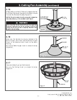
MOTOR
COUPLER
LOOSEN SET
SCREWS (2)
DOWNROD
Figure 13
3.13
Loosen the Two Phillips Head Set Screws in the Motor
Coupler for installation of the 4 .5” Downrod (Figure 13) .
Seat the 4 .5” Downrod in the Motor Coupler
(Figure 13) .
Rotate and align the 4 .5” Downrod holes with the Two
Holes in the Motor Coupler (Figure 13) .
CLEVIS PIN
HAIRPIN
CLIP
HAIRPIN
CLIP
CLEVIS
PIN
MOTOR COUPLER
Figure 14
3.14
Install the Clevis Pin and secure with the Hairpin Clip
(Figure 14) .
The Clevis Pin must go through the Motor Coupler
Holes . It is critical that the Clevis Pin in the Motor
Coupler is properly installed and securely tightened .
It is critical that the clevis pin in the motor coupler is
properly installed. Failure to verify that the clevis pin is
properly installed could result in the fan falling.
WARNING
!


