9
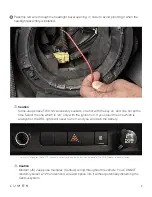
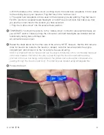
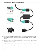
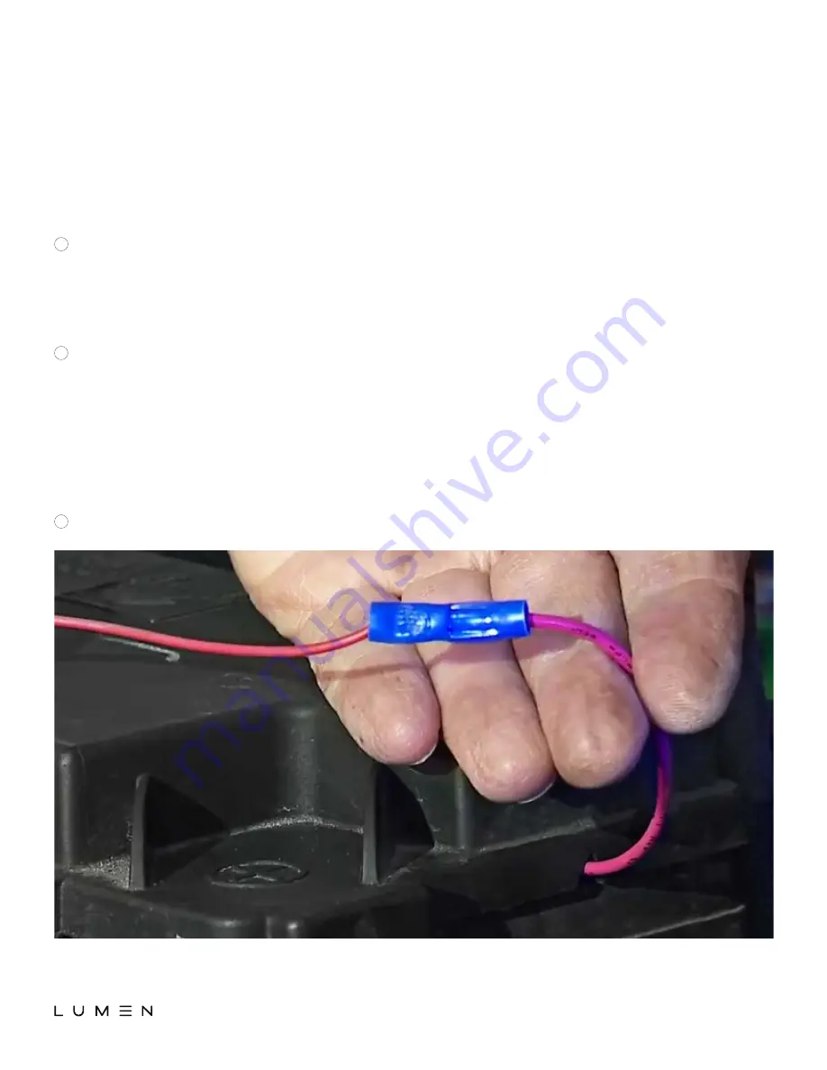
TEMPORARILY connect the red wire to the ‘‘Add-a-circuit’’ connector (use electrical tape), as
you will NOT want to finalize (crimp) the connection until both headlights are installed and all
functionality testing has confirmed that
all connections are correct.
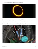
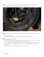
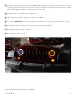
Repeat the steps above for the other side of the vehicle. NOTE, however, that the 2nd red wire
does not need to be routed to the fuse box; instead, route this red wire across the engine
compartment, and connect it to the 1st red wire. Secure all wiring.
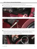
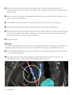
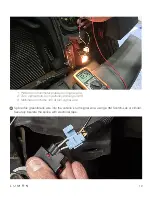
Note: It is important that lid fuse box lid can be closed completely. Once functionality has been
confirmed, create a channel for the wire to pass through the fuse box wall without being
pinched or the fuse box being compromised. The picture below shows the completed wire
passing through the fuse box (red box). This channel was created
using a triangular file.
Proceed to Step 3.
F
G
H
b.
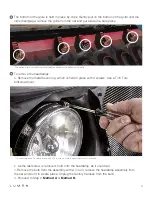
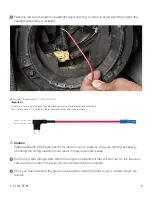
The upper fuse receptacle is to be used for the accessory you are adding. Plug that fuse in.
For DRL function of a sealed beam headlight, a 10 AMP fuse is sufficient. But make sure that
you use the correct fuse for the location you have selected.
c.
Plug the ‘‘Add-a-circuit’’ into the selected fuse position.
a.
With the blades of the ‘‘Add-a-circuit’’ pointing down, the lower fuse receptacle is to be used
for the existing fuse in your fuse box. Plug that fuse in the ‘‘Add-a-circuit’’.


