LSIS XBL-EIMT Скачать руководство пользователя страница 77


Chapter 5. Communication Parameters   


5-25 


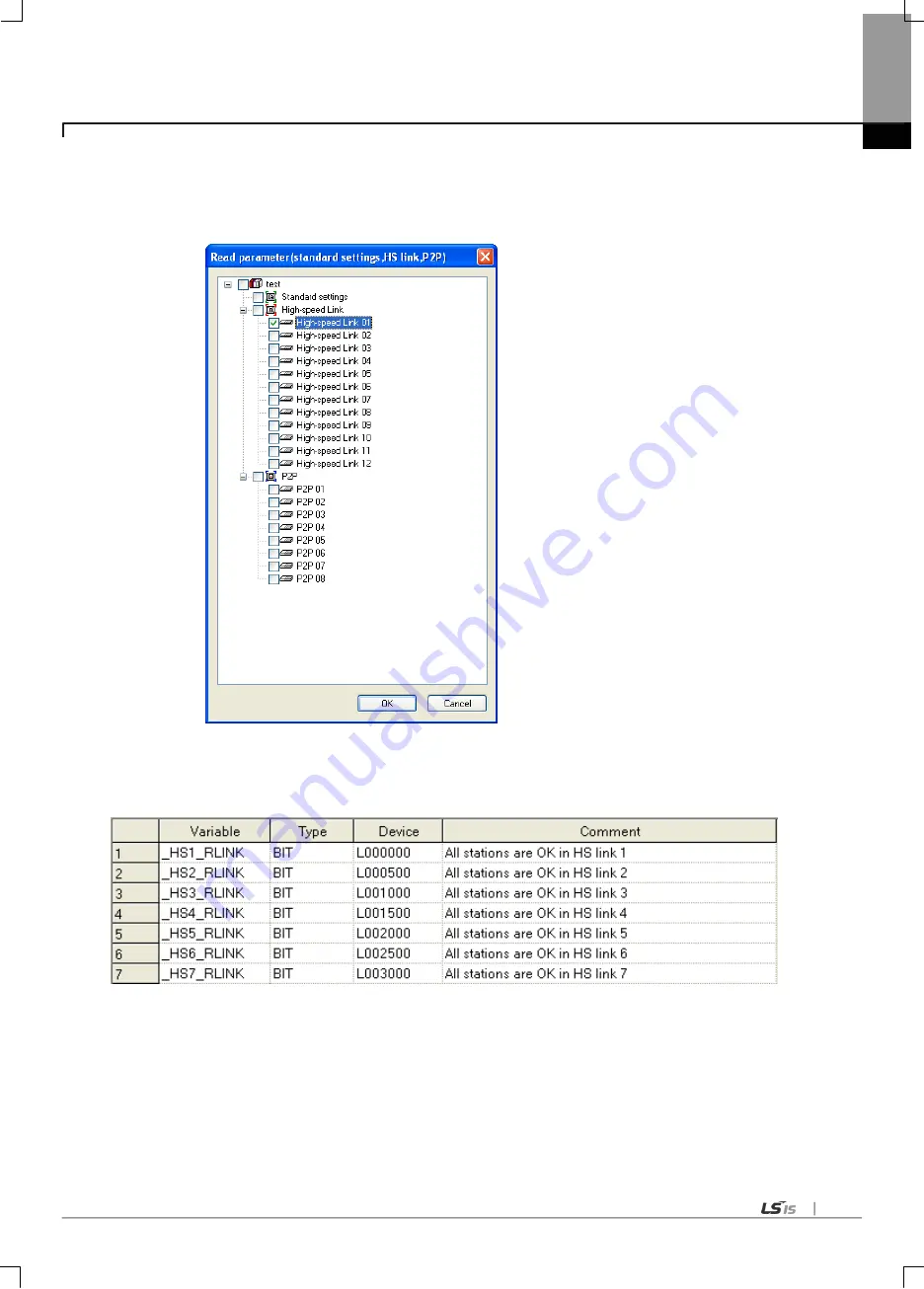
(4) Read high speed parameter 

Select „Read Parameter‟ from the Online menu. Check the desired parameter and click Confirm button to read the high 

speed link parameter. 


(5) High speed link information 

The high speed link information is provided to the XG5000 user as user keyword for use in programming. 

 
                  Type of high speed link flags   


Содержание XBL-EIMT

Страница 1: ... partner Programmable Logic Controller RAPIEnet I F Module User s Manual Read this manual carefully before installing wiring operating servicing or inspecting this equipment Keep this manual within easy reach for quick reference XGL EIMT XGL EIMF XGL EIMH XOL EIMT XOL EIMF XBL EIMT XGT Series http eng lsis biz ...

Страница 2: ...me applicable instruction is violated This symbol indicates the possibility of severe or slight injury and property damages if some applicable instruction is violated Moreover even classified events under its caution category may develop into serious accidents relying on situations Therefore we strongly advise users to observe all precautions properly just like warnings The marks displayed on the ...

Страница 3: ...ut signals are designed to be turned off and stopped for safety However there are cases when output signals remain active due to device failures in Relay and TR which can t be detected Thus you are recommended to install an addition circuit to monitor the output status for those critical outputs which may cause significant problems Never overload more than rated current of output module nor allow ...

Страница 4: ... PLC power is off If not electric shock or damage on the product may be caused Be sure that every module is securely attached after adding a module or an extension connector If the product is installed loosely or incorrectly abnormal operation error or dropping may be caused In addition contact failures under poor cable installation will be causing malfunctions as well Be sure that screws get tigh...

Страница 5: ...ns Secure terminal screws tightly applying with specified torque If the screws get loose short circuit fire or abnormal operation may be caused Securing screws too tightly will cause damages to the module or malfunctions short circuit and dropping Be sure to earth to the ground using Class 3 wires for FG terminals which is exclusively used for PLC If the terminals not grounded correctly abnormal o...

Страница 6: ...nstalling or disassembling the module let all the external power off including PLC power If not electric shock or abnormal operation may occur Keep any wireless equipment such as walkie talkie or cell phones at least 30cm away from PLC If not abnormal operation may be caused When making a modification on programs or using run to modify functions under PLC operations read and comprehend all content...

Страница 7: ...Safety Instructions Safety Instructions for waste disposal Product or battery waste shall be processed as industrial waste The waste may discharge toxic materials or explode itself Caution ...

Страница 8: ... Number of modules available by CPU types new model added 2 Specification added Ch1 3 2 Ch2 2 V 1 2 10 09 XGB RAPIEnet added V 1 3 11 05 How to enable link through flag added Ch 5 5 2 The number of User s manual is indicated right part of the back cover Copyrightⓒ 2005 LSIS Co Ltd All Rights Reserved ...

Страница 9: ...anual describing online function such as programming print monitoring debugging by using XGI XGR CPU XGK XGB Instructions Programming User s Manual User s manual for programming to explain how to use instructions that are used PLC system with XGK XGB CPU XGI XGR Instructions Programming User s Manual User s manual for programming to explain how to use instructions that are used PLC system with XGI...

Страница 10: ...1 Installation Environment 3 1 3 2 Precaution for Handling 3 6 3 3 Sequence from installation to operation 3 7 3 3 1 RAPIEnet I F Module for PLC 3 7 3 3 2 RAPIEnet I F module for PC 3 8 3 4 Parameter setting in the XG PD 3 9 3 4 1 Parameter setting 3 9 3 5 I OAllocation and Device Information 3 10 3 5 1 I O allocation 3 10 3 6 Installation 3 15 3 6 1 Installation of XGL EIMT and XOL EIMT 3 15 3 6 ...

Страница 11: ... the parameter according to service 5 23 5 4 1 High speed link service 5 23 5 4 2 P2P Service 5 26 5 5 Operation Start up 5 27 5 5 1 XG PD setting 5 27 5 5 2 When operating in high speed link service 5 28 5 5 3 Operating in P2P service 5 34 Chapter 6 High speed Link 6 1 Introduction 6 1 6 2 HS link Tx Rx Data Processing 6 2 6 3 Operation Sequence through High speed Link 6 3 6 4 HS link parameters ...

Страница 12: ...mote modules 10 4 10 4 Media information diagnosis 10 8 10 4 1 Media information 10 8 10 4 2 View error details 10 9 10 5 Troubleshooting 10 10 10 5 1 Diagnosis through communication Module LED 10 10 10 5 2 Diagnosis of Communication Module through XG5000 10 11 10 5 3 Checking module healthiness with system log 10 11 Appendix A 1 Terminology A 1 A 2 List of Flags A 3 A 2 1 List of Special Relays F...

Страница 13: ...ical ports 10 100BASE TX 2 optical ports 100BASE FX and hybrid 10 100BASE TX 100BASE FX according to the media type The Module is an interface module for data transmission between PLCs using these ports To create a program refer to the following manuals together XG5000 user manual XGK instruction XGK user manual XGI XGR instruction XGI XGR user manual When configuring communication module system p...

Страница 14: ...ancy function 8 Optical electrical and hybrid modules are provided for various control networks overcoming the limitation in distance Built in switching function enables construction of ring and line topology without additional switch or hub with reduced wiring and improved flexibility in installation 9 Provides alarm function for station number conflict 10 Auto Cross Over function is provided for...

Страница 15: ...an use this table for system construction considering the number of communication modules Classification XGK XGI XGRnote1 XGB PC I F Card CPUH CPUH CPUA CPUS CPUE CPUU CPUH CPUS CPUE CPUH F CPUH T XBC Max number of modules using high speed link 12 note2 2 1 Max number of modules using P2P 8 note2 2 Max number of module including the modules using exclusive services 24 note2 2 1 Note 1 The RAPIEnet...

Страница 16: ... etc XOL EIMF Note 1 The above program is downloadable form the website below If Internet is not available it is also possible to use it from Installation CD ROM by visiting the close agency Internet Website http www lsis biz 2 XG5000 and XG PD are programmable through RS 232C port of CPU module and USB For the cable type refer to XGT Catalog Product Exhibit USB 301A K1C 050A 1 4 2 XG PD XG PD is ...

Страница 17: ... d In the system diagnosis window from the online menu place the mouse pointer on the pertinent communication module e Double click the communication module or right click the mouse button Select detail information of the communication module Fig 1 4 2 Checking module s version by XG PD 2 Check by product s case label Each communication module is with module s product info on its external case If ...

Страница 18: ...tact discharge IEC61131 2 IEC61000 4 2 Radiated electromagnetic field noise 80 1 000 MHz 10V m IEC61131 2 IEC61000 4 3 Fast transient bust noise Segm ent Power supply module Digital analog input output communication interface IEC61131 2 IEC61000 4 4 Voltage 2kV 1kV 8 Environment Free from corrosive gasses and excessive dust 9 Altitude Up to 2 000 ms 10 Pollution degree 2 or less 11 Cooling Air coo...

Страница 19: ... excessive dust 7 Altitude Less than 2 000m 8 Pollution degree Less than 2 9 Cooling method Air cooling Table2 1 2 General specification for PC I F card N0ote 1 IEC International Electrotechnical Commission An international nongovernmental organization which promotes internationally cooperated standardization in electric electronic field publishes international standards and manages applicable est...

Страница 20: ... zone CSMA CD Frame error check CRC 32 X32 X26 X23 X2 X 1 Max equipment no note1 PLC 12 2 PC 1 Equip able location PLC XGK CPUU H XGI CPUU Main base extension step 7 XGK CPUE Main base extension step 1 XGK CPUA S XGI CPUH S Main base extension step 3 XGR CPUH F XGR CPUH T Main base XBC Main base extension PC Empty PCI slot Normal communication guarantee Max 3 600 packet sec note2 Max 1 200 packet ...

Страница 21: ...g and remote connection service may be abnormal The amount of packet is applied to only High Speed Link communication The amount of packet of normal communication guarantee is applied to only RX 3 For XGB data size per sec is maximum 10Kbyte sec If there are more TRX data communication may not be normally conducted So adjust your network load 4 When starting the initial communication 2 3 sec is ne...

Страница 22: ...dia interrupt Load by the frame coming from the media Determines the amount of load according to packet per second Max load of RAPIEnet module by media interrupt about 3600 packet sec How to check XG PD online system diagnosis media information Broadcast RX monitoring When the maximum amount f load is exceeded RAPIEnet operates abnormally Abnormal communication diagnosis unavailable remote connect...

Страница 23: ...ime and High Speed Link communication period HS link Comm Period ms CPU scan time ms Max no of TX block Time to process TX frame ms 5 5 or less 4 2 Over 5 No guarantee 10 5 or less 8 4 10 or less 4 2 Over 10 No guarantee 20 5 or less 16 8 10 less 8 4 20 or less 4 2 Over 20 No guarantee 50 5 or less 32 16 10 or less 16 8 20 or less 8 4 50 or less 4 2 Over 50 No guarantee 100 5 or less 64 32 10 or l...

Страница 24: ... set P2P ON P2P service is set OFF P2P service is not set PADT ON XG5000 remote connecting OFF XG5000 remote connection cancel RING ON Ring network Flicker Change from Ring to Line OFF Line network RELAY ON In case of Frame relay LNK ON Network link configuration ACT Flicker Send receive frame CHK ON There are duplicated modules in the same network FAULT ON There is module whose station number is ...

Страница 25: ...tation number if position of switch is wrong there may be error in setting the station number LED Status Details P Power ON Power on OFF Power on or power part abnormal S Status ON CPU normal OFF CPU abnormal L1 Link 1 ON CH1 network link configuration A1 ACT 1 Flicker CH1 send receive frame L2 Link2 ON CH2 network link configuration A2 ACT 2 Flicker CH2 send receive frame L LED Display Switch for...

Страница 26: ...ed Phonetic Data Low grade of video signal STP or S STP Double shielded cable Shielded core and Individually Pair cable Max 500MHz Phonetic Data Video signal Substitute for 75Ω coaxial cable Notes 1 UTP Unshielded Twisted Paired Copper Cable FTP Overall Foiled Twisted Paired Copper Cable STP Overall Shielded and Shielded Individually Pair Twisted Paired Copper Cable 2 Patch Cable or Patch Cord Con...

Страница 27: ...opment all over the world as STP structure 3 Classification based on fire UL standard Classifi cation Heat Time Length of fire Smoke suppression Reference CMP 88 kW 20 min 73m or less Restriction For ceiling without duct High voltage Plenum cable UL 910 Plenum test CMR 150 kW 30 min 3 6m or less Non Restriction Vertical installation Non high voltage Non Plenum cable UL 1666 Riser test CM 21 kW 20 ...

Страница 28: ... of multi mode fiber optic cable MMF Connector SC type connector Diameter of optical fiber 62 5 125μm 62 5μm fiber optic core and 125μm outer cladding Wavelength used 1 350 nm Attenuation 2dB 1 000m or less Near end crosstalk Attenuation 11dB or less Notes 1 Since the type of the connectable cable used for communication module differs from each other based on the system configuration and its envir...

Страница 29: ...control panel waterproof and dustproof b No continuous impact or vibration shall be expected c Not to be exposed to the direct sunlight d No dew shall be caused by rapid temperature change e Ambient temperature shall be kept 0 55 2 Installation Work a No wiring waste is allowed inside PLC when wiring or drilling screw holes b To be installed on a good location to work on c Don t let it installed o...

Страница 30: ...agreementwithhookforfixationoffouredgesandhookforconnectionatthebottom c Afterconnection getdownthehookforfixationattheupperpartandlowerpartandfixitcompletely 4 Detachmentofmodule a Getupthehookforfixationofupperpartandlowerpartanddisconnectit b Detachthemodulewithtwohands Don tforceover appliedforce Module fixation Hook Hook for module fixation ...

Страница 31: ...ed at DIN rail a In case of installing at DIN rail PullhookforDINrailatthebottomofmoduleandinstallitatDINrail PushhooktofixthemoduleatDINrailafterinstallingmoduleatDINrail b Incaseofinstallingatpanel YoucaninstallXGBcompacttypemainunitatpaneldirectlyusingscrewhole UseM4typescrewtoinstalltheproductatpanel 2 Ø 4 5 screw hole Panel HOOK for DIN rail ...

Страница 32: ...tandattachment 1 Incaseheightofwiringductislessthan50mm exceptthis40mmorabove 2 Incaseofequippingcablewithoutremovingnearmodule 20mmorabove 3 Incaseofconnectortype 80mmorabove 7 Moduleequipmentdirection a Foreasyventilation installlikethefollowingfigure b Don tinstalllikethefollowingfigure Panel PLC 20 or above 3 30 or above 1 30 or above 1 5 or above 5 or above 1 ...

Страница 33: ...Distancewithotherdevice Toavoidradiationnoiseorheat keepthedistancebetweenPLCanddevice connectorandrelay asfarasthefollowingfigure DeviceinstalledinfrontofPLC 100 orabove DeviceinstalledbesidePLC 50 orabove 100mm or above 50mm or above 50mm or above ...

Страница 34: ...side the top of the module when wiring d Get rid of foreign materials if any e Don t install or remove the module while powered on f Use standard cable only and let it installed within the maximum distance specified g Let the communication cable free from the surge and inductive noise generated by or from the alternating current h Don t let wiring too close to hot device and material or in direct ...

Страница 35: ...d link parameter downloading and link enable Execute high speed link communication Begin Check the functions and specification to be used Install module on the base Check base slot position Connect module and device with cable set module station No Turn power on Check module LED state RUN green Connect XG PD and XGK XGI CPU with cable Read IO information at XG PD After Read IO Information the modu...

Страница 36: ...PC If the station No is same with other RAPIEnet I F Module on the network conflict will occur Connect the PC I F card with another network Construct the system using jig appropriate for the medium Turn power on Check the LED of the PC I F Check that the P Power and S Status LED on the PC I F card are lit Install device driver PC I F card cannot be used without device driver Carry out programming ...

Страница 37: ...t 0 11 P2P block P2P function READ WRITE Conditional flag XGT device Command type Single Continuous Data type Bit Byte Word Double Word Long Word No of variables 1 4 Destination station On Off Destination station No 0 63 Setting Read area Save area Data size 2 High speed link parameter Parameter Setting item Details Setting PLC PC HS link Mode Send Receive Station No 0 63 Block No 0 63 Read area X...

Страница 38: ... of I O no of 12 slot base is as below 0 1 2 3 4 5 6 7 8 9 10 11 P0 P3F P40 P7F P80 P11F P120 P15F P160 P19F P200 P23F P240 P27F P280 P31F P320 P35F P360 P39F P400 P43F P440 P47F c Allocation of I O no Variable type 1 If assigned installation module by I O parameter the assigned point is allocated 2 The slot not assigned by I O parameter shall be allocated automatically according to actual install...

Страница 39: ...59F P2600 P263F Power P2640 P267F P2680 P271F P2720 P275F P2760 P279F P2800 P283F P2840 P287F Slot no 0 1 2 3 5 4 6 7 P3200 P323F P3240 P327F Power P3280 P331F P3320 P335F P3360 P339F P3400 P343F P3440 P347F P3480 P351F Slot no 0 1 2 3 5 4 6 7 P3840 P387F P3880 P391F Power P3920 P395F P3960 P399F P4000 P403F P4040 P407F P4080 P411F P4120 P415F Slot no 0 1 2 3 5 4 6 7 P4480 P451F P4520 P455F Power ...

Страница 40: ... 7 P0160 P016F P0170 P017F Power P0180 P018F P0190 P019F P0200 P020F P0210 P021F P0220 P022F P0230 P023F Slotno 0 1 2 3 5 4 6 7 P0240 P024F P0250 P025F Power P0260 P026F P0270 P027F P0280 P028F P0290 P029F P0300 P030F P0310 P031F Slotno 0 1 2 3 5 4 6 7 P0320 P032F P0330 P033F Power P0340 P034F P0350 P035F P0360 P036F P0370 P037F P0380 P038F P0390 P039F Slotno 0 1 2 3 5 4 6 7 P0400 P040F P0410 P041...

Страница 41: ...ositiononwhichaspecialmoduleismountedorthenumberisnotlimited UnlikedigitalI Omodule aspecialmoduleisnotallocatedforanyconstantI Onumber A special module is controlled by the exclusive function block and automatically allocated for thememory Forinstance theI Onumberof12slotbaseisallocatedasfollows Remark 1 Thebasisbasehasitsbasenumberas 0 andtheextensionbasehasaswitchtosetthebasenumber 2 Operations...

Страница 42: ...0 2 2 15 2 3 0 2 3 15 2 4 0 2 4 15 2 5 0 2 5 15 2 6 0 2 6 15 2 7 0 2 7 15 Slot no 0 1 2 3 5 4 6 7 3 0 0 3 0 16 3 1 0 3 1 15 Power 3 2 0 3 2 15 3 3 0 3 3 15 3 4 0 3 4 15 3 5 0 3 5 15 3 6 0 3 6 15 3 7 0 3 7 15 Slot no 0 1 2 3 5 4 6 7 4 0 0 4 0 16 4 1 0 4 1 15 Power 4 2 0 4 2 15 4 3 0 4 3 15 4 4 0 4 4 15 4 5 0 4 5 15 4 6 0 4 6 15 4 7 0 4 7 15 Slot no 0 1 2 3 5 4 6 7 5 0 0 5 0 16 5 1 0 5 1 15 Power 5 ...

Страница 43: ...cross cable 1 TD 1 1 1 3 2 TD 2 2 2 6 3 RD 3 3 3 1 6 RD 6 6 6 2 4 5 7 8 Not used Remark 1 Since the structure of 10 100BASE TX cable is vulnerable to external noise the cable needs to be stranded as twisted two lines twisted with each other between cables of the pin No 1 and 2 of TD and TD and between cables of the pin No 3 and 6 of RD and RD so to be strong against noise 2 Contact professional ma...

Страница 44: ...ents either at this time Especially be careful not to bend the cable intensely which may cause not only damage but also distance between pairs Max radius of curvature 4 pair cable 4 times of external diameter Cable with 25 or more pairs 10 times of external diameter f Max tension strength during wiring shall not exceed 110 N 11 3 Kgf based on 4 pair cable g Jumper wire and patch code shall be wire...

Страница 45: ...he module s Rx with the other module s Tx Remark 1 Since the optical cable is vulnerable to impact pressure folding and pulling pay good attention to its treatment The optical contact between the connector and the end of the cable may have communication errors if contaminated which may result in unavailable communication If the cable is installed outdoors additional countermeasures are required to...

Страница 46: ...Chapter 3 Installation and Test Operation 3 18 3 6 3 Installation of XGL EIMH Fig 3 6 3 100BASE TX 100BASE FX installation LC 8 pin RJ45 Plug Twisted pair cable ...

Страница 47: ...onnector until connected firmly If cable connection is unstable serious error may occur to communication e If remote communication cable is connected keep the cable far away from power line or inductive noise f Since the coaxial cable is not flexible it is to be diverged min 30cm away from the connector in communication module If the cable is bent at a right angle or transformed compulsorily cable...

Страница 48: ...tension base Among those 8 modules can be used as P2P service If you use dedicated protocol all 24 modules can be used Applicable system configuration is described below 4 1 Available System Configuration 4 1 1 Ring type system with electric module 100Mbps Ethernet TP Total Max 64 Node XGT Series PLC System Fig 4 1 1 System configured by electric module Max 64 stations XGL EIMT XGL EIMT XOL EIMT ...

Страница 49: ...Chapter 4 System Configuration 4 2 XBL EIMT XBL EIMT XOL EIMT Max 64 stations Fig 4 1 2 System configured by XBL EIMT ...

Страница 50: ...iguration 4 3 4 1 2 Ring type system with optical module Total Max 64 Node XGT Series PLC System 100Mbps Ethernet Fiber Optic Cable Fig 4 1 3 System configured with optical module Max 64 stations XGL EIMF XGL EIMF XOL EIMF ...

Страница 51: ... type system with combined module 100Mbps Ethernet TP 100Mbps Ethernet Fiber Optic Cable Total Max 64 Node XGT Series PLC System Fig 4 1 4 System configured combined module Maximum 64 stations XGL EIMF XOL EIMT XGL EIMH XGL EIMH XGL EIMT XOL EIMF ...

Страница 52: ...h optical module 100Mbps Ethernet Fiber Optic Cable or TP XGT Series PLC System Total Max 64 Node Fig 4 1 5 Line type system configured optical module Electric module and combined module also can be used to configure line type system Maximum 64 stations XGL EIMF ...

Страница 53: ...e maximum size is 200 words Communication period can be set from 5ms to 1 second according to the contents of the communication Communication can be implemented simply by setting parameters Large volume of data can be exchanged periodically due to high speed internal data process The following table is HS link setting specification Table 5 1 1 High Speed Link parameter Parameter Lower menu Setting...

Страница 54: ...reception of the desired frame d Maximum 64 independent P2P blocks can be defined in each module The table below presents the specification for setting up P2P parameters Paramete r Sub menu Setting Setting Range Description P2P P2P Block P2P function WRITE Transmission READ Reception Start up condition Special flags bit contact point Set up the operational conditions of frame Data type BIT Set up ...

Страница 55: ...vents Classification High speed link P2P Basic data unit 1word 16 bits Available by data type E g BIT BYTE WORD DWORD LWORD Period 5ms 10ms 20ms 50 ms 100 ms 200 ms 500ms 1s Executed when the P2P Enable REQ condition is met timer Available modules Between RAPIEnet Communication Modules Between RAPIEnet Communication Modules Station No designation Set the high speed station No for reception in XG P...

Страница 56: ...rt or USB port is necessary 3 Hard Disk At least 100MB and more space is necessary 4 Mouse Mouse to connect with the computer is necessary 5 Monitor Monitor should have 1024 x 768 and higher resolution 6 Windows Compatible with Windows 2000 XP However XG5000 may be shut down if several applications including other programs are executed in Windows 98 ME due to limited memory Please execute XG5000 b...

Страница 57: ... folder to install XG5000 into If you want to change the folder click Browse button and make or select a new folder XG5000 needs about 30M Bytes of installation space in hard disk which will ask you to select a disk with enough capacity If the installation space is not enough a warning message will be displayed to make the following progress unavailable 7 After a folder is selected click Next butt...

Страница 58: ...Chapter 5 Communication Parameters 5 6 8 Check installation folder and click Next button 9 Installation will be started as shown below 10 Wait a second for the installation to be complete ...

Страница 59: ...he driver shall be additionally installed 1 Ensure that Drivers folder is created in the folder where XG5000 is installed and there are 2 driver files of GmUSBD sys and GmUSBD inf in the Drivers folder If there is no folder or driver file reinstall XG5000 2 Turn PLC Power on and connect USB connector with PC If connection is established Find New Hardware Wizard Dialog Box will be displayed to ask ...

Страница 60: ...s 5 8 4 Among driver searching options select Search for the best driver in these locations and check Include this location in the search 5 Click Browse button On Browse Folder Dialog Box select Drivers folder where XG5000 is installed ...

Страница 61: ...arts searching for the driver files in the selected folder 7 If the computer found the most suitable device driver you will be asked to decide to install the selected device driver Since USB device driver operated stably based on Windows OS you may click ContinueAnyway button ...

Страница 62: ... 5 Communication Parameters 5 10 8 If the device driver has been installed completely the Installation Complete Dialog Box will be displayed as follows Click Finish button to end the installation of the driver ...

Страница 63: ... select Manage on the menu 2 Computer Management Dialog Box will be displayed as shown in the figure below On the left tree list of Dialog Box click Computer Management Local System Tools Device Manager in regular order The items displayed on the right list may be different according to devices installed on the computer a Normal case The USB device driver for XGT PLC has been installed successfull...

Страница 64: ...essfully if the following figure is displayed If the USB driver for XGT PLC is not installed successfully reinstall the USB driver for XGT PLC in the following steps Steps 1 On the device driver with the icon with an exclamation mark click the right button of the mouse Select Update Driver on the menu ...

Страница 65: ...next sequence is manually the same as in Installation of Device Driver If the USB driver for XGT PLC is not installed successfully reinstall the USB driver for XGT PLC in the following steps Steps 1 If the device driver has been installed incorrectly or in error execute H W Update Wizard Select the option Installation from a list or specific location Advanced and click Next ...

Страница 66: ...Chapter 5 Communication Parameters 5 14 2 On search and installation options select Don t Search I will choose the driver to install and click Next 3 Click Have Disk on the Dialog Box below ...

Страница 67: ...se button 5 From the Browse File Dialog Box move to the folder XG5000 is installed in Select drivers folder to display GmUSBD inf file With this file selected click Open button 6 On the item of Copy manufacturer s files from a directory with the file of the device driver will be displayed Click OK button ...

Страница 68: ...s 5 16 7 On Show compatible hardware list of the device driver Select Dialog Box select LSIS XGSeries driver and then click Next button 8 Hardware Installation Dialog Box will appear Click ContinueAnyway to go on with the installation ...

Страница 69: ...Chapter 5 Communication Parameters 5 17 9 Completing the Hardware Update Dialog Box will appear Click Finish button to end the installation of the driver ...

Страница 70: ...ed RAPIEnet I F module depends on On Off line status as described below 5 3 1 Off line registration This method is used when the user writes the parameter related with communication about communication module that is not connected with PLC 1 Execute the XG PD and select File New File or click the icon 2 Input the project name file location and PLC type the user is using 3 In the Standard settings ...

Страница 71: ...hs Local Remote 1 Remote 2 For remote connection refer to the Chapter 8 Remote Connetcion 3 If connection succeeds lower menu of online is activated 4 In order to check the currently mounted modules select Online Read IO Information or click the icon Then all currently mounted communication modules in the basic and extension bases are searched and shown in the Project window 5 If previous informat...

Страница 72: ...d the parameter saved in the PLC follow the below sequence 1 Select the Open from PLC 2 After setting the connection type and depth click the connection 3 Input the project name and file location and click the OK 4 The user can check the setting value of standard settings and P2P saved in the PLC ...

Страница 73: ...unted REPIE net I F module Communication module setting window is appeared on the main window 2 Read I O Information Read the IO information of the currently mounted modules by Online Read IO Information after connection 3 Checking the operation a Select Oline System Diagnosis or click the icon b Click the right button at the relevalet module and click the Frame Monitor or Status By Service to che...

Страница 74: ...e Parameter Writes the parameter edited in the XG PD Read Parameter Reads the parameter from the PLC Enable Link Enables the communication of communication module set by P2Por high speed link Upload Download file This menu is not used by the user SyCon upload Reads the data set in the SyCon System diagnosis Monitors the operation status of communication module Reset Reset PLC Reset Reset individua...

Страница 75: ... to 200 words for the communication communication cycle from the min 20 ms up to 10 sec based on the communication details It is easy to use since communication with correspondent station is available only through simple parameters setting And it is also useful for periodic process of lots of data at a time thanks to high processing speed of the internal data 1 Communication module configuration I...

Страница 76: ... each station Do not allocate multiple block numbers under the same station number 200 words can be set to one block The maximum link points are 12 800 words The serial No representing the order of registration from 0 to 127 not in relation with the order of communication d Read area enabled when the block type is transmission This is the area setting of the device for transmission e Storage area ...

Страница 77: ...arameter from the Online menu Check the desired parameter and click Confirm button to read the high speed link parameter 5 High speed link information The high speed link information is provided to the XG5000 user as user keyword for use in programming Type of high speed link flags ...

Страница 78: ...of the XG PD and communication module without changing the OS of the CPU module d Modification during running can be done by adding changing or deleting individual parameter block e Maximum 64 parameter blocks can be monitored Fig 5 4 2 Example of P2P parameter setting P2P service provides read and write functions to support reading and writing of the partners memory P2P Function Description Remar...

Страница 79: ... parameters for the PLC2PLC communication module The parameters set up by user can be written downloaded in the RAPIEnet I F communication module and read uploaded from the RAPIEnet I F communication module 2 Connection setting a Select Online Connection settings or click icon b After setting the connection option according to user click the connection 3 Reading IO information Select Online Read I...

Страница 80: ...er 5 Communication Parameters 5 28 Fig 5 5 1 XG PD basic window 5 5 2 When operating in high speed link service 1 Parameter setting Following window will appear when the high speed link parameter is selected ...

Страница 81: ...C Base Number Select the No of the base of the installation Slot number Select the No of the slot of the installation Communication period settings Period type Set the data transmission period Output data setup in case of emergency CPU error Set the output data at CPU error CPU stop Set the output data at CPU stop When the communication module has been setup following window will appear ...

Страница 82: ...ck number Set the No of the transmission and reception blocks Read area Address Memory area of the module to be transmitted Read area Word size Size Word Set the size of data for transmission Save area Address The area in the correspondent station where the received data will be stored Save area Word size Size Word Set the size of data for reception 3 Write high speed link parameters XG PD Online ...

Страница 83: ...r and click Confirm button to read the high speed link parameter setting Fig 5 5 2 Read Parameter window 5 Link Enable a Select Online Link Enable or click icon b Select the set up high speed link and click Write 6 Operation check a Select Online System Diagnosis or click icon b Click the pertinent module Right click the mouse and select frame monitoring or service status to check that the communi...

Страница 84: ...OF BOOL FX16528 P2P enable disable setting XGK Flag Data type Device Description _HS1_ENABLE_STATE BIT F09600 HS link 1 enable disable current state _HS2_ENABLE_STATE BIT F09601 HS link 2 enable disable current state _HS3_ENABLE_STATE BIT F09602 HS link 3 enable disable current state _HS4_ENABLE_STATE BIT F09603 HS link 4 enable disable current state _HS5_ENABLE_STATE BIT F09604 HS link 5 enable d...

Страница 85: ... _P2P5_ENABLE_STATE BIT F09624 P2P5 enable disable current state _P2P6_ENABLE_STATE BIT F09625 P2P6 enable disable current state _P2P7_ENABLE_STATE BIT F09626 P2P7 enable disable current state _P2P8_ENABLE_STATE BIT F09627 P2P8 enable disable current state _P2P1_REQ BIT F10320 P2P1 enable disable request _P2P2_REQ BIT F10321 P2P2 enable disable request _P2P3_REQ BIT F10322 P2P3 enable disable requ...

Страница 86: ...when P2P Parameter is selected a Communication module setting In the P2P window click the P2P01 to register the module currently in the slot The function of each setting is as follows Classification Description Communication Module Settings Type Select PLC2PLC Base Select the No of the base Slot Select the No of the slot ...

Страница 87: ...station Set when correspondent station is required Destination station number Set up the No of the correspondent station Setting Read area Set up the XGT device area Save area Data size Set up the size of the data to be transmitted or received Address The address of the N device area of the CPU module where the data in the variable setting window will be stored This address cannot be set up by use...

Страница 88: ...nable or click icon 2 Select the P2P which is set up and click Write e Operation check 1 Select Onloine System Diagnosis or click icon 2 Click the pertinent module Right click the mouse and select frame monitoring or service status to check that the communication is normal or not ...

Страница 89: ...ns are as specified below 1 HS link block setting function a If there are many Tx Rx areas up to 96 blocks can be set 32 for Tx and 64 for Rx respectively b 200 words are available for a block c Max link points available are 19 200 words 2 Tx Rx period setting function Tx Rx period can be set per block by user for the areas where especially fast Tx Rx is required and not required respectively in a...

Страница 90: ... M0100 d M0110 data of 10 words is transmitted to No 1 block There are 64 blocks for Tx data and 128 blocks for Rx data in the HS link parameters The block number can be set 0 63 for transmission or receiving The Tx side needs only to decide which data to read and which block to send to without setting the correspondent station No when transmitting the data Table 6 2 1 Diagram of HS link processin...

Страница 91: ...ption period 5ms 1s High speed link setting register list 1 Mode transmission or reception transmission cannot be set up Designate correspondent station No for reception 2 Station No 0 63 3 Block No XGK I 0 127 TX count 64 RX count 128 blocks are available XGB 0 64 TX count 64 RX count 64 blocks are available TRX data is classified by station number and block number 4 Read area Save area 5 Size 1 ...

Страница 92: ...f XG PD 1 Execution of XG PD If XG PD is executed for the first time the screen will be displayed as shown in Fig 6 4 1 Click XG5000 s Tools Network Manager or click XG PD icon of XG5000 Fig 6 4 1 Basic screen of XG PD 2 Basic setting In the XG PD screen select Online Access to access PLC Select Online Read IO Information The RAPIEnet I F Module installed on the base appears in the basic setting w...

Страница 93: ...3 Fig 6 4 3 Initial setting screen of High speed link b Setting of communication module and communication period Double click one of the HS links 01 12 on the Fig 6 4 3 screen to open the setting screen of communication module and communication period where communication module and communication period can be specified Fig 6 4 4 Initial setting screen of High speed link ...

Страница 94: ... the communication period The communication period will be applied identically to the whole Tx Rx blocks Up to 4 blocks of data can be sent at a time Even if this is exceeded the data will be divided into 4 block unit for transmission with which the data size of a block has noting to do Emergency output data setting CPU Error Set up the output data at CPU error Latch latched to the output just bef...

Страница 95: ...mber Duplicated block number is not allowed Other station number Duplicated block number is allowed Read area Address Set device area used when receiving Setting device XGK P M L K D T C U N R ZR XGI M I Q R W It shall not be duplicated with the device address being used in program Read area Word size Size Word Set data size to send Setting unit Word Setting range 1 200 Save area Address Set devic...

Страница 96: ...heck the applicable HS link and then click OK Fig 6 4 7 Write Parameter Screen 5 High speed link parameter setting Click Online Enable Link in XG PD check the applicable HS link and then click Write If HS link is enabled on the module s LED display HS LED will be On when HS link starts Fig 6 4 10 Link Enable Screen ...

Страница 97: ...also monitor the HS link status using the monitor function of the HS link information Prior to its application the user is requested to check the reliability of the Tx Rx data through HS link information of Run link and Link trouble when operating several PLCs with HS link used Table 6 5 1 below shows functions and definition of the HS link information Classification Run link Link trouble Tx Rx st...

Страница 98: ... period the applicable bit will be On and if not it will be Off 4 Operation mode _HSxMODE 0 127 x HS link no 1 12 As individual information it shows the operation status of HS link parameters on the register list up to 127 registered items operation mode information just like the max register number If the station specified in the register item is in Run mode the applicable bit will be On and if i...

Страница 99: ... and there select Flag directly to select and register HS link information flag one by one on the screen of the variable flags list At this time since _HSxSTATE n _HSxERR n _HSxMOD n and _HSxTRX n are the flags of array type the user needs directly to select the array numbers which stand for the register numbers inside the parameters 2 High speed link monitor from the XG PD diagnosis services a Se...

Страница 100: ...A screen shown in Fig 6 5 3 will appear Fig 6 5 3 Autoscan screen In theAutoscan window shown in Fig 6 5 3 place the mouse pointer on the RAPIEnet I F Module for which the high speed link service is to be monitored Right click the mouse button and select Service Statuses The high speed link statuses of other RAPIEnet I F Modules on the network can be monitored as shown in Fig 6 5 4 Fig 6 5 4 High ...

Страница 101: ... sequence with P2P used is as follows XG PD Connect to CPU Register communication module P2P Parameter setting Register up to 128 blocks Online Write parameter Download parameters Online Enable Link P2P Enable 7 2 P2P Instruction 1 P2P Instruction There are two P2P Instructions used for user to prepare programs Type Purpose Read Reads the specified area of the correspondent station to save Write S...

Страница 102: ... the communication modules to execute P2P service so to set P2P blocks on the empty P2P register window as above In order to define P2P service for PLC2PLC installed on Base 0 Slot 7 to execute select one among P2P 1 8 first Fig 7 3 2 Setting screen of communication module Item Details Type Select a module desired to use Base Select a base where PLC2PLC module is installed Slot Select a slot where...

Страница 103: ...Instructions Write Read can be set up Conditional flag Conditions for executing instruction can be set up Data type Data type can be set up Bit Byte Word Dword Lword No of variables No of variables per block to be communicated can be set up Destination station Correspondent station can be set up to set station No Destination station number No of the correspondent station for P2P communication can ...

Страница 104: ...s P2P function Select P2P function READ Conditional flag 1 Define the time pint of the READ function is started 2 If set to IX0 0 0 the function starts when IX0 0 0 is set Data type 1 In the READ function define the data type of the area used in the P2P block 2 LWord DWord Word Byte and Bit can be selected No of variables 1 Define the No of the areas where READ function will be executed per index ...

Страница 105: ...ow will appear as shown in Fig 7 3 7 2 WRITE It is used to write the data of the self station on an optional area of the correspondent station when the defined event happens If Bit FX147 is set 5 words from MW120 of the self station will be saved on MW200 of the correspondent station No 5 with the following setting ...

Страница 106: ...ig 7 4 1 Parameters setting screen Select desired P2P parameters and click OK to start to download 2 P2P service start P2P parameters after downloaded shall be enabled by user to start P2P service Select Online Enable Link to display the screen as shown below Fig 7 4 3 Parameters setting screen Among P2P parameters 0 7 presently operation P2P parameters are checked among which check P2P parameters...

Страница 107: ...ice from the XG PD system diagnosis a Select XG PD Connect Online System Diagnosis Fig 7 5 1 System Diagnosis b With the mouse cursor placed on XGL EIMH click the right mouse button and select Status by service to open Fig 7 5 2 as shown below where P2P service information can be checked Fig 7 5 2 P2P status for respective services ...

Страница 108: ...connected with each other via RAPIEnet in XG PD of Fig 8 1 1 To access the contents of PLC 1 station in the figure above Local connection is needed in XG PD s on line menu After finishing accessing the contents of PLC 1 disconnect the Local connection with Disconnect menu To access the PLC n station select PLC n by setting the Base and Slot No where RAPIEnet module is installed in the PLC 1 statio...

Страница 109: ...llowings explains remote 1 and remote 2 connections Fig 8 2 1 Remote connection Fig 8 2 1 shows an example remote stage 1 2 connection in the network system composed of two networks 8 2 1 Remote 1 connection If RS 232C cable used For remote stage 1 connection XG PD shall be in off line state At this state Select Online Connection Settings Fig 8 2 2 XG PD remote connection option to select PLC B s ...

Страница 110: ...trial times Retrial times to connect CPU 0 9 Fig 8 2 3 Detail setting window Item Details Network type Select a network type For RAPIEnet I F module select RAPIEnet Base number Select base number of a communication module at the local PLC for remote 1 connection Local communication module Slot number Select slot number of a communication module at the local PLC for remote 1 connection Remote 1 com...

Страница 111: ...ction failure the following message appears Figure 8 2 5 Connection failure window This appears when connection setting or line is abnormal When CPU type of the connected PLC is different from that of the currently opened project the following message appears Correct the CPU type Figure 8 2 6 In case of PLC type mismatch Remote 1 connection state is same as the connection state connecting RS 232C ...

Страница 112: ...C A s RAPIEnet Æ PLC B s RAPIEnet Æ PLC C s RAPIEnet For remote stage 2 connection XG PD shall be in off line state At this state Select Online Connection Settings and select Remote 2 at Depth Figure 8 2 7 Online Settings window Click Settings Then select Remote 1 tap Set a Remote 1 tap Fig 8 2 8 Details window remote 1 ...

Страница 113: ...pe Select a network type For RAPIEnet I F module select RAPIEnet Base number Base number of the communication module at remote 1 Remote 1 communication module Slot number Slot number of the communication module at remote 1 Remote 2 communication module Station number Station number of the communication module at remote 2 ...

Страница 114: ...ove Preview window is as follows Figure 8 2 10 Preview window of remote 2 connection If setting is complete exit from an option window and execute online connection Remote 2 connection state is same as the connection state connecting RS 232C cable to the target PLC of remote connection 2 You can use all items in the online menu ...

Страница 115: ... 2 words Table 9 1 1 I Oconfiguration and TRX data 1 HS link parameter setting In order to communicates like Table 9 1 1 at the system like Fig 9 1 1 write data TRX map like Table 9 1 1 Write HS link parameter and download it to PLC for communication like Table 9 1 1 Start the HS link by the following sequence a Connect XG PD to XGT CPU and set standard parameter b Write data TRX map c Set paramet...

Страница 116: ...APIEnet and define Base Number abd Slot Number After setting HS link set TRX parameter from index 0 For example in case of XGT station no 1 it consists of TX block 0 and RX block 0 After setting TRX area according to TRX data map set communication period according to 6 6 2 High Speed Link speed calculation Here it is set as default value 200ms Fig 9 1 3 Fig 9 1 5 shows results of parameter setting...

Страница 117: ...nder operation if user download HS link parameter Enable Link is canceled automatically and it is set after download 2 Write Parameter On XG PD select Online Write Parameter and check relevant HS link and press OK Fig 9 1 6 is screen of Write Parameter Fig 9 1 6 Screen of Write Parameter High Speed Link Write parameters about XGT system station no 1 2 3 ...

Страница 118: ...lculation Namely expression St P_Scan1 C_Scan P_Scan2 St HS link Max TX time P_Scan1 Max program scan time of PLC station no 1 P_Scan2 Max program scan time of PLC station no 2 C_Scan Max communication scan time At above expression P_Scan1 P_Scan2 is scan time of XGT PLC and we will assume that is 5ms respectively See Online PLC Information Performance for accurate scan time Expression C_Scan Th S...

Страница 119: ...h Speed Link Diagnosis service To check if system is normal at System Diagnosis click XGnet I F module with right button of mouse and select Status by Service and open HS Link service tap Fig 9 1 8 Screen of Status by Service HS link service ...

Страница 120: ...ration Details 1 2 Bit 2 of F9 READ Read MW10 20 30 and save MW0 1 2 2 3 Bit 3 of F9 READ Read 10 Word from MW100 and save MW10 3 4 Bit 0 of M5 WRITE Read MW0 1 2 and save MW10 20 30 4 5 Bit 3 of M6 WRITE Read 10 Word from MW10 and save MW100 Table 9 2 1 I O configuration and TRX data 1 Execute XG PD and connect to CPU of XGT station 1 2 To register P2P service register RAPIEnet module by using On...

Страница 121: ...it 2 of FW9 is set read MW10 20 30 of partner 2 and save them at MW0 1 2 of self station Fig 9 2 3 P2P block setting 1 Fig 9 2 4 P2P variable setting 1 b 2 When bit 3 of FW9 is set read 10 words from MW100 of station 3 and save them at MW10 Fig 9 2 5 P2P block setting 2 Fig 9 2 6 P2P variable setting 2 ...

Страница 122: ... 2 of self station and save them at MW10 20 30 of partner 4 Fig 9 2 7 P2P block setting 3 Fig 9 2 8 P2P variable setting 3 d 4 When bit3 of MW6 is set read 10 words from MW10 and save them MW100 of partner 5 Fig 9 2 9 P2P block setting 4 Fig 9 2 10 P2P variable setting 4 ...

Страница 123: ...0 Screen of Wirte Parameter P2P The downloaded P2P parameter is backed up regardless of power 6 Enable P2P link Though P2P parameter is downloaded normally P2P service doesn t start The user has to notify the operation Activate P2P service by using Online Enable Link of XG PD Fig 9 2 11 Screen of Enable Link P2P The started P2P service holds its status though power is off or reset ...

Страница 124: ...9 10 9 2 2 P2P Diagnosis To check if system is normal at System Diagnosis click XGnet I F module with right button of mouse and select Status by Service and open P2P service tap Fig 9 1 8 Screen of status by service P2P service ...

Страница 125: ... Access to access PLC and select Online System Diagnosis The local system diagnosis window will appear as shown in Fig 10 1 1 and the Module information window will appear beneath the system diagnosis window as shown in Fig 10 1 2 Fig 10 1 1 System diagnosis window Fig 10 1 2 Module information window When connected with extension bases click the extension base on the Module information window to ...

Страница 126: ...ates module s station No Range of indication 0 63 Option board type Indicates type of option board TP 2 ports electrical 2 ports HYBRID optical 1 port electrical 1 port FIBER 2 ports optical 2 ports Max link scan Max task execution time of OS ms Min link scan Min task execution time of OS ms Current link scan Current task execution time of OS ms MAC address Indicates MAC address Run Mode Additiona...

Страница 127: ...Scan window The text information on the top of the Auto Scan window is as follows Item Description Base No Indicates the base location of the local RAPIEnet I F MODULE Range of indication 0 7 Slot No Indicates the slot location of the local RAPIEnet I F MODULE Range of indication 0 11 Link Type Indicates the network type of the local RAPIEnet I F MODULE PLC2PLC Topology Shows network configuration...

Страница 128: ...truct the system connect cables b Turn power on check that all the link LEDs of the RAPIEnet I F Modules connected with cables c From the electrical ports of the modules whose Link LEDs are ON isolate cables and reconnect after 5 10 seconds d Conduct c hereinabove with all the modules whose cable lengths are to be measured However do not isolate both ends of cable e Conduct 3 above for the cables ...

Страница 129: ...nication module information window will appear as shown in Fig 10 3 4 Fig 10 3 4 Remote communication module information window For the details of the communication module information items in Fig 10 3 4 see 10 2 Communication Module Information 2 Remote service statuses Select Service Statuses from the menu tree in Fig 10 3 3 The Remote Service Status window will appear as shown in Fig 10 3 5 and...

Страница 130: ...Chapter 10 Diagnostic Function 10 6 Fig 10 3 5 Remote Service Status window P2P service Fig 10 3 6 Remote Service Status window high speed link service ...

Страница 131: ... Status high speed link service items see Chapter 6 High Speed Link Service 3 Remote media information Select Media Information from the menu tree in Fig 10 3 3 the Remote Media Information window will appear as shown in Fig 10 3 7 Fig 10 3 7 Remote Media Information window For the details of the media information items in Fig 10 3 7 see 10 5 Media Information Diagnosis ...

Страница 132: ...mation XGT server Total No of the frames communicated with XGT server service High speed link Total No of the frames communicated with high speed link service P2P Total No of the frames communicated with P2P service P2P Others Total No of the frames communicated with other services Media status information packets sec Broadcast Packets sec of the frames communicated by broadcasting Multi cast Pack...

Страница 133: ...t No of the frames failed to be transmitted by 16 times of transmission Delay Collision Detect Cnt No of the delay conflicts occurred in the line after transmission Lost Carrier Cnt No of carrier lost occurred in the transmission Carrier Not Detected Cnt No of failures to detect carrier during preamble transmission CRC Error Frame Receive Cnt No of frame occurrence for which CRC error was received...

Страница 134: ...ect 2 Check if link enable is On P2P Off during command service 1 Check if the command is input correctly 2 Check if connection is normal 3 Check if the menu Enable Link is On PADT Off during remote connection service 1 Check if the station No is correct for remote PADT connection 2 Check if PADT program s remote connection is released RING Off after ring configuration 1 Check if the connection an...

Страница 135: ...s abnormally in general whose status can be monitored simply through its dedicated program Fig 10 6 2 shows error warning information through PLC History on the XG5000 Online menu which can be resolved by referring to Details Remedy 10 5 3 Checking module healthiness with system log Healthiness of communication modules can be roughly checked with XG PD software Connect CPU module via RS 232C or US...

Страница 136: ... viewed 2 Flash area log When error or service provision cannot be checked with XG PD or to save the content of the current memory area in flash press the log switch on the front of the RAPIEnet I F Module The memory area log will be saved in the flash automatically Fig 10 5 4 shows the flash area log of System Log Fig 10 5 4 Flash area log of System Log ...

Страница 137: ...ision may occur The client who detects the collision tries to send again in a specific time 4 Ethernet A representative LAN connection system IEEE 802 3 developed by Xerox Intel and DEC of America which can send about 10Mbps and use the packet of 1 5kB Since Ethernet can allow various types of computers to be connected as one via the network it has been called a pronoun of LAN as a universal stand...

Страница 138: ...pecify detailed interface between machines in Low level for example which bit byte should go out through the line or high level of message exchange regulations as files are transferred through the Internet 13 Near end crosstalk Near end crosstalk affecting other near line is one of the disturbances made by electric or magnetic field of communication signal Near end crosstalk causes that some part ...

Страница 139: ...IT_END Modification complete during run Modification complete during run F0000C BIT _CMOD_KEY Run Mode Run Mode changed by key F0000D BIT _CMOD_LPADT Run Mode Run Mode changed by local PADT F0000E BIT _CMOD_RPADT Run Mode Run Mode changed by remote PADT F0000F BIT _CMOD_RLINK Run Mode Run Mode changed by remote communication module F00010 BIT _FORCE_IN Compulsory input Compulsory input status F000...

Страница 140: ...BIT _CPPRM_ER Communication module parameter Communication module parameter abnormal F0002C BIT _PGM_ER Program error Program error found F0002D BIT _CODE_ER Code error Program code error found F0002E BIT _SWDT_ER System watch dog System watch dog active F0002F BIT _BASE_POWER_E R Power error Base power abnormal F00030 BIT _WDT_ER Scan watch dog Scan watch dog active F0004 DWORD _CNF_WAR System wa...

Страница 141: ... 6 P2P parameter6 error F0005A BIT _P2P_WAR7 P2P parameter 7 P2P parameter7 error F0005B BIT _P2P_WAR8 P2P parameter 8 P2P parameter8 error F0005C BIT _CONSTANT_ER Fixed cycle error Fixed cycle error F0009 WORD _USER_F User contact point Timer available for user F00090 BIT _T20MS 20ms CLOCK of 20ms cycle F00091 BIT _T100MS 100ms CLOCK of 100ms cycle F00092 BIT _T200MS 200ms CLOCK of 200ms cycle F0...

Страница 142: ... equal F00123 BIT _GT GT flag ON if greater than F00124 BIT _GTE GTE flag ON if greater than or equal F00125 BIT _NEQ NEQ flag ON if not equal F0013 WORD _AC_F_CNT Inspected power cut Number of inspected power cuts displayed F0014 WORD _FALS_NUM FALS No FALS No displayed F0015 WORD _PUTGET_ERR0 PUT GET error 0 Main base PUT GET error F0016 WORD _PUTGET_ERR1 PUT GET error 1 Added base step 1 PUT GE...

Страница 143: ...FPU_LFLAG_U Underflow latch Latched if underflow found F00572 BIT _FPU_LFLAG_O Overflow latch Latched if overflow found F00573 BIT _FPU_LFLAG_Z Latch divided by 0 Latched if divided by 0 F00574 BIT _FPU_LFLAG_V Invalid calculation latch Latched if invalid calculation F0057A BIT _FPU_FLAG_I Incorrect error Reported if incorrect error found F0057B BIT _FPU_FLAG_U Underflow Reported if underflow foun...

Страница 144: ...pe 2 error Added base step 2 module type error F0099 WORD _IO_TYER3 Module type 3 error Added base step 3 module type error F0100 WORD _IO_TYER4 Module type 4 error Added base step 4 module type error F0101 WORD _IO_TYER5 Module type 5 error Added base step 5 module type error F0102 WORD _IO_TYER6 Module type 6 error Added base step 6 module type error F0103 WORD _IO_TYER7 Module type 7 error Adde...

Страница 145: ...ule RW 7 error Added base step 7 module Read Write error F0128 WORD _IO_IFER_0 Module IF 0 error Main base module interface error F0129 WORD _IO_IFER_1 Module IF 1 error Added base step 1 module interface error F0130 WORD _IO_IFER_2 Module IF 2 error Added base step 2 module interface error F0131 WORD _IO_IFER_3 Module IF 3 error Added base step 3 module interface error F0132 WORD _IO_IFER_4 Modul...

Страница 146: ... Write ON when writing Flash N block data F0164 DWORD _RBLOCK_ER_FL AG Flash error Error found during Flash N block service F1024 WORD _USER_WRITE_F Available contact Contact point available in program F10240 BIT _RTC_WR RTC RW Data Write Read in RTC F10241 BIT _SCAN_WR Scan WR Scan value initialization F10242 BIT _CHK_ANC_ERR Detect external serious error Detection of serious error in external eq...

Страница 147: ...uble will be On if one of those conditions 1 2 and 3 above occurs And if such a condition is back to normal it will be Off L000020 L00009F _HS1_STATE k k 000 127 Bit Array HS link parameter No 1 Block No k s general status displayed Displays the general status of the communication information for the specified parameter s respective data blocks HS1STATE k HS1MOD k _HS1TRX k _HSmERR k L000100 L0001...

Страница 148: ...ink No Larea address Remarks 2 L000500 L00099F Compared with HS link of 1 in Table 1 other HS link station number s flag address will be simply calculated as follows Calculation formula L area address L000000 500 x HS link No 1 In order to use HS link flag for program and monitoring use the flag map registered in XG5000 for convenient application 3 L001000 L00149F 4 L001500 L00199F 5 L002000 L0024...

Страница 149: ... 00 service abnormal execution times P2P parameter No 1 block No 0 service abnormal execution times displayed L006310 _P2P1_NDR01 Bit P2P parameter No 1 block No 01 service complete normally P2P parameter No 1 block No 1 service complete normally L006311 _P2P1_ERR01 Bit P2P parameter No 1 block No 01 service complete abnormally P2P parameter No 1 block No 1 service complete abnormally L00632 _P2P1...

Страница 150: ...1 block No 00 area device 3 to read saved N00015 _P1B00RS3 Word P2P parameter No 1 block No 00 area size 3 to read P2P parameter No 1 block No 00 area size 3 to read saved N00016 N00019 _P1B00RD 4 Device structure P2P parameter No 1 block No 00 area device 4 to read P2P parameter No 1 block No 00 area device 4 to read saved N00020 _P1B00RS4 Word P2P parameter No 1 block No 00 area size 4 to read P...

Страница 151: ...area size 2 to read saved N00052 N00055 _P1B01RD 3 Device structure P2P parameter No 1 block No 01 area device 3 to read P2P parameter No 1 block No 01 area device 3 to read saved N00056 _P1B01RS 3 Word P2P parameter No 1 block No 01 area size 3 to read P2P parameter No 1 block No 01 area size 3 to read saved N00057 N00060 _P1B01RD 4 Device structure P2P parameter No 1 block No 01 area device 4 to...

Страница 152: ...evice 4 saved N00081 _P1B01WS 4 Word P2P parameter No 1 block No 01 saved area size 4 P2P parameter No 1 block No 01 saved area size 4 saved Notes 1 If P2P parameters are to be specified with XG PD used for N area the setting will be performed automatically And its modification during Run is also available by P2P dedicated command 2 Since the addresses of N area available are classified according ...

Страница 153: ...Appendix A 17 A 3 Dimension Unit mm XGL EIMT EIMF EIMH ...

Страница 154: ...Appendix A 18 XOL EIMT EIMF ...

Страница 155: ...Appendix A 19 XBL EIMT ...

Страница 156: ... On Is the comm module correctly installed Does the same failure occur again H W of the comm module failure Contact a S Center Check power supply voltage Check correct installation environment Install comm module correctly Is the operation normal Conduct troubleshooting for the error Operation No yes yes Yes Yes Yes No No No No H W failure ...

Страница 157: ...wer supply OK Is the comm module correctly installed Comm module or CPU H W failure Contact A S Center Check power supply voltage Adjust control the environment to meet the specifications Install comm module on the base correctly Yes No Yes Yes No No Interface failure End ...

Страница 158: ...orrectly installed on the main base Is the power supply OK Is the installation environment OK Install the error module correctly Install comm module correctly Check power supply voltage Adjust control the environment to meet the specifications Comm module H W failure Contact A S Center Conduct troubleshooting for the CPU Yes No Yes Yes Yes No No No No Yes Interface failure during operation End ...

Страница 159: ...m correct Of the register items is there any duplication in the block No for the same station Replace battery Download program and parameters again Turn the link permission setting ON Correct the link setting to match with the network type station No or slot No of the respective slot Correct the station No referring to 6 1 4 Correct the duplicated register No Reduce the number of the transmission ...

Страница 160: ... item correct Of the register items is the communication area appropriate In the link permission setting turn the link permission setting to ON Turn the link permission setting to ON Correct the link setting to match with the network type station No or No of the slot Correct station No setting referring to 6 1 4 Correct communication area range by referring to CPU type and 6 1 4 Check correct acco...

Страница 161: ...of receiving blocks Max process time ms 1 5 3 max 4 2 5 over No warranty 2 10 3 max 8 4 8 max 4 2 10 over No warranty 3 20 3 max 32 16 8 max 16 8 18 max 4 2 20 over No warranty 4 50 3 max 64 32 8 max 32 16 18 max 16 8 48 max 8 4 50 over No warranty 5 100 3 max 128 64 8 max 64 32 18 max 32 16 48 max 16 8 98 max 8 4 100 over No warranty 6 200 3 max 128 64 8 max 128 64 18 max 64 32 48 max 16 8 98 max...

Страница 162: ...hen there is error in making a P2P request frame at the main unit it doesn t send a request frame H03 P2P_VAR_COUNT_ERR The number of variable of read request is different from the number of variable of response frame H05 P2P_RESP_FUNC_ERR Instruction of response frame is unknown H0B P2P_MAX_BLOCK_NO_ERR P2P block ID is 32 or above H0C P2P_PARAM_DOWN _ERR The request comes from a main unit before ...

Страница 163: ...circumstances where the expectations exceed that of the science and technology level when LSIS produced the product 6 Problems caused by natural disaster 3 This warranty is limited to the PLC itself only It is not valid for the system which the PLC is attached to Environmental Policy LSIS Co Ltd supports and observes the environmental policy as below LSIS considers the environmental preservation a...

Страница 164: ...0 8328 6754 Fax 86 20 8326 6287 e mail chenxs lsis com cn LSIS Chengdu Office _ Chengdu China Address 12FL Guodong Buiding No 52 Jindun Road Chengdu 610041 P R China Tel 86 28 8612 9151 9226 Fax 86 28 8612 9236 e mail comysb lsis biz LSIS Qingdao Office _ Qingdao China Address YinHe Bldg 402 Room No 2P Shandong Road Qingdao City Shandong province 266071 P R China Tel 86 532 8501 6068 Fax 86 532 85...

Отзывы: