AC/DC Specifications
6-3
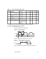
6.1.2 AC Timing Diagrams for L64777
Figure 6.1 illustrates the TS input timing.
Figure 6.1
TS Input Timing
Figure 6.2 illustrates the reset timing of the L64777.
Figure 6.2
L64777 RESET Timing Diagram
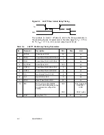
Figure 6.3 illustrates the 3-state delay timing of the L64777 bus.
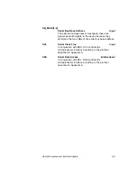
I
IN
Input Current Leakage
V
DD
= Max, V
IN
=
V
DD
or V
SS
−
10
±
1
10
mA
I
IN
Input Current Leakage
w/Pullup
V
DD
= Max, V
IN
=
V
DD
or V
SS
−
62
−
215
−
384
mA
I
IN
Input Current Leakage
w/Pulldown
V
DD
= Max, V
IN
=
V
DD
or V
SS
−
62
−
215
−
384
mA
I
DD
Quiescent Supply Current
V
IN
= V
DD
or V
SS
2
mA
I
CC
Dynamic Supply Current
ICLK = 54 MHz max,
PLL MODE 2 PCLK
90 MHz
VDD = Max
50
mA
1. Specified at V
DD
= 3.3 V
±
5% at ambient temperature over the specified range.
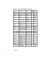
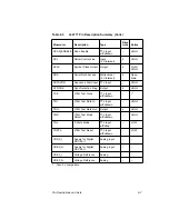
Table 6.3
L64777 DC Characteristics (Cont.)
Symbol Parameter
Condition
1
Min
Typ
Max
Units
Inputs
3 & 6
2 & 5
1 & 4
8
7
ICLK
RESET
9
10
Содержание L64777
Страница 1: ...L64777 DVB QAM Modulator Order Number I14031 A Technical Manual June 2000...
Страница 10: ...x Contents...
Страница 14: ...1 4 Introduction...
Страница 90: ...5 10 Signals...
Страница 110: ...A 8 Programming the L64777 in Serial Host Interface Mode...
Страница 116: ...C 2 Monitoring Device Internal Signals...
Страница 124: ......

