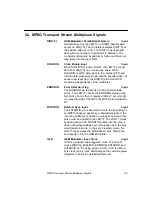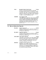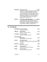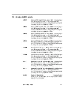
NCO-Related Registers
4-13
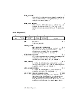
FIFO_INT
FIFO Interrupt
R/W 0
This bit enables generation of an interrupt in response to
a FIFO alarm. The reset value is 0.
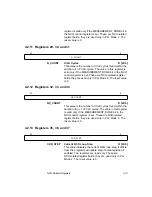
4.2.4 Register 15
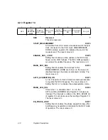
TEST
Reserved Test
R/W [7:0]
This register is reserved for LSI Logic production testing;
each bit field must be set to zero. The reset value is 0.
4.2.5 Registers 16, 17, and 18
INIT_STEP
R/W [23:0]
This value is the initial NCO step parameter. It is loaded
into the NCO when the most significant portion is written.
These are NCO-related register fields; they are used only
in PLL Mode. Bits 8 and 23 are reset to 0; all other bits
are reset to 1.
4.2.6 Registers 19 and 20
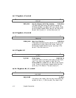
NCO_GAIN
NCO Loop Bandwidth Adjustment
R/W [15:0]
The L64777 can use this parameter to adjust the NCO
loop bandwidth. The value becomes valid on writing to
the most significant portion. These are NCO-related
register fields; they are used only in PLL Mode 2. Bit 8 is
reset to 1; all other bits are reset to 0.
7
0
TEST
23
0
INIT_STEP
15
0
NCO_GAIN
Содержание L64777
Страница 1: ...L64777 DVB QAM Modulator Order Number I14031 A Technical Manual June 2000...
Страница 10: ...x Contents...
Страница 14: ...1 4 Introduction...
Страница 90: ...5 10 Signals...
Страница 110: ...A 8 Programming the L64777 in Serial Host Interface Mode...
Страница 116: ...C 2 Monitoring Device Internal Signals...
Страница 124: ......

