14 //ADJUSTABLE BED FRAME - OWNER’S MANUAL
STEP 3: CONNECTING THE BARS
1. /LIWWKH¿UVW&URVVEDU
(D)
and place one end of it
into a slot on the Side Rail
(Right)
(A).
Ensure the Thread on the
Side Rail (the metal part
facing upwards) passes
through the hole at the
end of the Crossbar.
2. Place a Crossbar Knob (E)
onto the thread connect-
ing the Side Rail and the
Crossbar. Turn the Knob
counter-clockwise until it
is hand tight.
D
E
REMOVE STRAPPING TAPE
REMOVE PROTECTIVE MATERIAL
CAUTION
Risk of minor or moderate injury through crushing
The Side Rails are not secured while they are standing alone. If they fall over, this may lead to
minor or moderate injury through crushing.
• Do not attempt to stand the Side Rails upright before they are connected to the Crossbars
• Be careful not to knock over the Side Rails
• Ensure that you are wearing suitable footwear while assembling the Bed Frame
3. Repeat steps 1 and 2 for
the second Crossbar.
D
A
15
ADJUSTABLE BED FRAME - OWNER’S MANUAL //
STEP 4: CONNECTING THE CABLES
1. Insert the 4 Motor Cables
from the Side Rails
(A, B)
into
the Plug Ports on the Control
Box
(I)
. Ensure that the color
of the Plug matches the color
of the Plug Port.
2. Insert the Power Converter
Cable
(J)
into the Control
%R[/D\WKH&DEOHÀDWDORQJ
WKHÀRRUWRUHGXFHWKHULVNRI
tripping.
CAUTION
Risk of minor or moderate injury through crushing
While screwing in the Crossbar Knobs, you will need to lift the moving parts of the Side Rails.
Allowing these parts to fall may lead to minor or moderate injury through crushing.
• Ensure moving parts do not fall down during assembly
CAUTION
Risk of minor or moderate injury through crushing
*ULSSLQJWKH6LGH5DLOVPRYLQJSDUWVPD\OHDGWRPLQRURUPRGHUDWHLQMXU\WKURXJKFUXVKLQJ
• 'RQRWWRXFKPRYLQJSDUWVZKHQOLIWLQJRUPRYLQJWKH6LGH5DLOV2QO\JULSWKH¿[HGSDUWV
A
B
J
I
4. Connect the Crossbars
(D)
to the Side Rail (Left)
(B)
as shown in steps 1-3.
D
D
B
A
R
16 //ADJUSTABLE BED FRAME - OWNER’S MANUAL
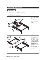
1. Turn over the Base Plat-
form
(H)
DQG OD\ LW ÀDW
across the center of the
Bed Frame. The Net
should face downwards.
2. Ensure that the Platform
is correctly positioned.
There should be 2 Mount-
ing Holes on each Side
Rail
(A, B)
either side of
the Platform.
3. Use 4 Platform Screws
(N)
WR¿[WKH3ODWIRUPE\KDQG
Turn each screw until it is
hand-tight.
H
A
B
N
STEP 5: MOUNTING THE BASE PLATFORM
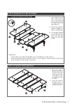
1. Lay the Base Platform
(H)
upside down across
the Bed Frame. The Net
should face upwards.
2. Lay the Control Box
(I)
in-
side the Net on the Base
Platform.
H
I
BASE
4x
CAUTION
Risk of minor or moderate injury through tripping
While mounting the Platforms, you may have to step over the Power Cable. Tripping over the
Cable may lead to injury.
• Be careful not to trip over the Cable


