background image

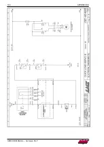
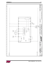
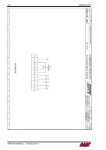
APPENDICES


147


SERVICE MANUAL – QL Servo S3-T 


Содержание QUICK LOAD SERVO S3 T BARFEED

Страница 1: ...For CNC machine tool peripherals it s LNS then all the rest QUICK LOAD SERVO S3 T BARFEED Service Manual 9 021 04 02 EN US ...

Страница 2: ...GENERAL SERVICE MANUAL QL Servo S3 T ...

Страница 3: ...AL SERVICE MANUAL QL Servo S3 T IMPORTANT READ THIS MANUAL CAREFULLY BEFORE USING AND RETAIN FOR FUTURE REFERENCE Published 08 2020 LNS America 2020 9 021 04 01 EN V00 0 Service manual Printed in LNS America ...

Страница 4: ...SURING CELL ADJUSTMENT SQ3 23 PUSHER REVERSING DISTANCE ADJUSTMENT 25 MAGAZINE AND LOADING FINGER ADJUSTMENT 26 CALIBRATION OF THE LOADING TABLE 27 FINDING SOFTWARE PLC VERSIONS 28 SOFTWARE UPDATE 28 PLC BATTERY REPLACEMENT 29 3 MECHANICAL EQUIPMENT 30 BAR MAGAZINE 30 LOADING TABLE 34 PUSHER CARRIER 35 LOADING PUSHER 36 FEEDING PUSHER 36 RETRACTION 39 KIT FOR SQUARE BARS OPTION 39 KIT FOR QUICK PA...

Страница 5: ...MACHINE 96 10 TROUBLESHOOTING 98 ALARMS 98 SEQUENCE DIAGRAM 102 SEQUENCE LISTING 103 MITSUBISHI ALARM LIST MRJ 4 105 MITSUBISHI WARNING LIST MRJ 4 109 MITSUBISHI ALARMS CAUSE AND SOLUTIONS 110 PLC INPUTS OUTPUTS 116 PRODUCT MANUALS 117 AFTER SALES SERVICE 119 11 APPENDICES 120 GLOSSARY 120 WIRING DIAGRAM 021 40 620F CE MRJ 4 121 WIRING DIAGRAM 021 40 650F CE DCS MRJ4 131 WIRING DIAGRAM 021 40 622C...

Страница 6: ...GENERAL SERVICE MANUAL QL Servo S3 T ...

Страница 7: ...ted components from other manufacturers In the case of these components their respective manufacturers have carried out a risk assessment and have declared that their design is fully compliant with the European standards in force Information regarding the proper use of these integrated components is available in the component instructions and provided by the various manufacturers The feeder compli...

Страница 8: ...not avoided may result in serious or fatal injury CAUTION Type and origin of danger Consequences of non compliance with the warning What to do to avoid danger Warnings of a potentially dangerous situation which if not avoided may cause minor injuries NOTICE Type and origin of danger Consequences of non compliance with the warning What to do to avoid danger Warnings of a potentially dangerous situa...

Страница 9: ...left right front and rear refer to the direction of use of the machine COPYRIGHT Any reproduction recording or distribution of all or part of this manual in any form or by any means mechanical photographic audio or other is strictly prohibited without the express written permission of LNS LNS accepts no liability for any errors in this manual and any resulting complications The product names indic...

Страница 10: ...e interface or inside the electrical cabinet while the bar feeder or the lathe is powered on It is strictly forbidden to bridge or remove circuit breakers and main switches especially safety switches To ensure the safety of components and personnel observe the points indicated for lifting and moving the bar feeder It is expressly forbidden to stay near the suspended load or in the operating area o...

Страница 11: ...evel of the lathe even if the lathe lies only over three points and cannot be perfectly levelled Should the level of the bar feed system not correspond to that of the lathe the feeding pusher might touch the inside of the spindle Place the bar feeder as close as possible behind the headstock lathe The distance between the front of bar feeder and the back of headstock lathe should be as small as po...

Страница 12: ...can be placed on the linear belt rail to verify the y axis and on the retract rails to verify the x axis Use the leveling screws shown with arrows on the retract to adjust unit to level 3 Carefully loosen the 16 screws located in the slots on the base of the unit This will allow the unit to be adjusted up and down ...

Страница 13: ...l tube 2 supplied with the bar feed adjust the unit so that the pusher is centered up and down at the back of the spindle Make sure that the unit raises or lowers uniformly 5 Once the pusher is centered up and down tighten the 16 screws to secure unit and recheck the level of the unit 1 2 ...

Страница 14: ... when centering to the rear of the spindle and the front of the bar feed when centering to the rear of the collet Once the pusher is centered at the back of the collet recheck the alignment at the back of the spindle by pulling the pusher back Continue until the pusher is centered at the rear of the spindle and the rear of the collet 7 Once the bar feed has been aligned anchor it using the inch an...

Страница 15: ...Once the power and air have been hooked up the bar feed must be calibrated After calibrating the bar feed return to this procedure and move on to Step 11 for the final alignment 11 For final alignment load a bar into the v channel and verify that it can be loaded into the spindle of the lathe without hitting the sides of the spindle or spindle liner If the bar hits side to side the alignment will ...

Страница 16: ... complete this procedure Bar feeder switch on Loading table in lower position Pusher at the mechanical home position Bar feed in STOP mode 1 Open the main access cover 2 Measure the distance of the End of Bar bushing 3 Pull the carrier away from the home position 4 Loosen up the setscrews to release the pusher ...

Страница 17: ... Remove the pusher from the bar feed 7 Put the new pusher in the bar feed 8 Push the guide bushing in the front ring 9 Place the rear end of the pusher in the carrier and tighten the setscrews 10 Adjust the End of Bar bushing to the distance measured at setp 2 11 Close the main access cover ...

Страница 18: ...his procedure Bar feeder POWER OFF 1 Open the main access cover 2 Loosen the four nuts on the motor mount plate 3 Using a lever ex screwdriver raise the motor to create tension on the belt 4 Holding the belt taut tighten the four nuts on the motor mount plate 5 Once the tension is adjusted remove the lever and close the main access cover ...

Страница 19: ...e main access cover 2 Loosen the four nuts on the motor mount plate 3 On each end of the carriage unit are black plastic end caps In the center of the end cap on either side right above the belt is an opening with a 3mm Allen head tensioning screw inside Turn the screw CW to add tension to the belt and CCW to release tension 4 Once the tension is adjusted remove the lever and close the main access...

Страница 20: ...EMENT INFORMATION The following conditions must be met to complete this procedure Bar feeder POWER on Bar feed in STOP mode 1 Remove the front panel on the sub base 2 Remove the two rear panels on the sub base 3 Remove the four screws holding on the chain guard cover plate ...

Страница 21: ...otor 5 Disconnect the SQ4 cable from the mounted proximity switch 6 Disconnect the M2 cable from the XP1 connector and remove the bad motor 7 Insert the new motor and connect the M2 cable to the XP1 connector 8 Connect the SQ4 cable to the new mounted proximity switch and reconnect the chain ...

Страница 22: ... MANUAL QL Servo S3 T 9 While pulling the motor toward the front of the bar feed to keep the chain taut tighten the two screws for the motor assembly 10 Reassemble the chain guard 11 Reassemble the front and rear panels ...

Страница 23: ...l home position against the reference plate 1 Open the main access cover 2 Adjust the hex bolt underneath the SQ5 proximity switch just far enough to get a strong signal from the switch and tighten down Note any slight movement forward of the carrier should deactivate the proximity sensor 3 Close the main access cover 4 Press the STOP key on the remote control station to clear and reset the alarm ...

Страница 24: ...he bar feed for access to the front of the unit 2 Open the main access cover 3 Place a piece of 6mm or smallest diameter stock available into the v channel and set parameter NEW BAR STOCK DIAMETER for the corresponding diameter Note the stock must be straight to obtain the ideal adjustment 4 Push the stock up so that it is sticking out the front of the bar feeder Turn the gain adjustment on the me...

Страница 25: ...ain adjustment CCW to the minimum position 7 From the minimum position slowly turn the gain adjustment CW until the sensor detects the bar Once the sensor detects the bar continue to turn the gain CW another turn 8 Remove the material from the v channel and close the main access cover 9 Press the STOP key on the remote control station to clear the Main Access Cover Open alarm ...

Страница 26: ...n Bar feed in STOP mode 1 Press the icon for manual mode 2 Run the pusher forward until the tip of the pusher sags and is touching the spindle or spindle liner if one is installed Note if the pusher does not touch the spindle before the End of Bar position is reached then the default value will remain as the value for the Pusher Reversing Distance parameter If this is the case then return the push...

Страница 27: ...onditions must be met to complete this procedure No stock on the magazine Bar feed in STOP mode PROCEDURE ROUND PROFILED Rotate the loader rack adjustment axle CCW to increase the slope of the magazine until the indicator on the side of the magazine references the profiled material Note if there is not enough adjustment on the threaded rod remove the pin and lift the magazine up to the next hole a...

Страница 28: ...ppears Press the F1 key 5 Three icons appear F1 lowers the table F2 ESC exit without saving F4 raises the table Each time F1 or F4 is pressed the vertical position of the table is changed by 0 25mm For larger adjustments press and hold the button so that the table moves continuously 6 Once the required position is reached press the F3 ENTER key to confirm that you wish to recalibrate the unit to t...

Страница 29: ...OWER on 1 In the electrical cabinet open the PLC cover 2 Insert the card containing the new software in the M1 labeled bay A chamfer avoids any bad insertion 3 With a sharp object press on the little button labeled Run Halt for approx 3 seconds until the LED located at its left blinks 4 The PLC is rebooted and the new software is loaded This operation takes max 10 seconds When the barfeed has save...

Страница 30: ...te this procedure Bar feeder POWER on 1 In the electrical cabinet open the PLC cover 2 Take the battery support out of the bay labeled BATT 3 Replace the battery with an identical type Check that the battery is in the right direction Insert back the battery support in its bay Close the PLC cover and the electrical cabinet ...

Страница 31: ...y if bars with a small diameter start to pile up the gradient can be decreased A protection grid prohibits access to the magazine during the automatic cycle In manual mode the grid which is fitted onto hinges can be retracted to enable the operator to perform all the required maintenance operations Under no circumstances may a rotating bar protrude past the end of the lathe spindle The maximum aut...

Страница 32: ...ANUAL QL Servo S3 T LAYOUT OF THE ELEMENTS Designation Description 1 Magazine table 2 Protection grid for magazine table 3 Rear limiter 4 Loading table support 5 Fingers for bar selection 6 Holding rod SQ11 Grid closed safety switch ...

Страница 33: ...spindle from the entry to in front of the collet Lift the protection grid Unscrew the retaining screws for the rear limiter Place the limiter at the distance measured in the spindle L max measuring from the front limiter Tighten the retaining screws Apply the adhesive marker to the bar magazine This marker will enable the position of the limiter to be set at a later date without the need to measur...

Страница 34: ...to move the rear limiter to reduce the loading time Lift the protection grid Install a bar on the bar magazine pressing against the front limiter Move the rear limiter 1 millimeter behind the bar Check the parallelism of the limiter by rolling the bar on the magazine Tighten the retaining screws Close the protection grid Edit the corresponding parameter To facilitate movement of the bars on the ma...

Страница 35: ...tion of the material When the table A is in the lowered position the pusher B is opposite the spindle C The pneumatic cylinders are active the table is raised and selects the bar D which is pressing against the stops E on the bar magazine 2 Guiding of the material When in the raised position the loading table is aligned with the spindle The bar can therefore be inserted into the spindle To ensure ...

Страница 36: ...le 3 Table in the raised position The loading pusher is opposite the spindle the pusher is not locked 4 Table in the lowered position The pusher is opposite the spindle the pusher is locked onto the carrier The length of the pushers is fixed and does not depend on the spindle length As a safety measure the pushers are equipped with a mechanical stop For loading of tubes profiled bars or short bars...

Страница 37: ...Three feeding pushers are necessary to cover the entire range of the QUICK LOAD SERVO III barfeed system Each pusher has a defined range of operation Pusher diameter Diameter Range 6 35 mm 1 4 6 mm 15 mm 1 4 1 2 12 mm 1 2 16 mm 32 mm 2 3 1 1 4 25 mm 1 33 mm 120 mm 1 1 4 4 7 2 extra roller supports intended to bolster the support of bars of small diameter are furnished with the 6 35 mm diameter pus...

Страница 38: ...e loading table to the working position lowered 2 Open the protection cover 3 Unscrew the retaining screws A on the mechanical stop 4 Close the protection cover 5 Move the pusher to its end of bar position 6 Open the protection cover 7 Slide the mechanical stop against the guiding bushing B then move it back 2 millimeters 8 Tighten the retaining screws 9 Close the protection cover LOADING OF TUBES...

Страница 39: ... to penetrate the spindle F the tip must be turned at a diameter 4 millimeters less than the spindle passage F The tip must be adapted before being fitted on the pusher Procedure 1 Bar feeder in STOP position 2 Unscrew the threaded dowel E securing the tip on the pusher 3 Remove the standard tip C 4 Install the special tip D pushing it fully into the pusher 5 Secure the tip with the retaining scre...

Страница 40: ...with a retraction system which allows the operator to move it Designation Description 1 Rails 2 Bearings 3 Mounting hooks 4 Levers 5 Transverse beam longitudinal depending on the direction fitted 6 Non return device SQ12 Safety switch KIT FOR SQUARE BARS OPTION An adapter for square bars must be used to enable to bar to be oriented from the table to 120 from the center of the spindle This kit incl...

Страница 41: ...of the same length may be loaded with a special pusher A The loading procedure is simplified and the loading time can be reduced by adapting the interface with the lathe This kit includes a specific pusher with a diameter of 12 mm which can be adjusted to the length of the part to be loaded ...

Страница 42: ...MECHANICAL EQUIPMENT SERVICE MANUAL QL Servo S3 T ...

Страница 43: ...timal operation of the bar feeder a minimum pressure of 5 bar 75 psi 500 kPa is mandatory LAYOUT OF THE ELEMENTS Designation Description 1 Air handling unit with pressure control unit 2 Solenoid valve block 3 Pneumatic cylinders for vertical movement of the table 4 Pusher locking pneumatic cylinder ...

Страница 44: ... mm G1 4 push in fitting 4 Manometer 5 Decanter 6 Discharge screw ADJUSTING THE SERVICE PRESSURE 1 Unlock the adjusting knob by pulling it upward 2 Turn the regulator until the pressure gauge indicates a correct value 3 Reduce the pressure Turn the regulator counter clockwise Increase the pressure Turn the regulator clockwise 4 Lock the adjusting knob by pushing it downward ...

Страница 45: ...operating pressure should be kept at 5 bar PNEUMATIC BATTERY The pneumatic battery includes the control and monitoring elements of the bar feeder pneumatic circuit LAYOUT OF ELEMENTS Designation Description 1 Solenoid Valve YV1A YV1B 2 Pressure switch SP1 3 Silencer ...

Страница 46: ...PNEUMATIC EQUIPMENT SERVICE MANUAL QL Servo S3 T ...

Страница 47: ...If there is a fault that you believe is electrical contact LNS or a local representative SAFETY COMPONENTS These components are installed to ensure safe use of the bar feeder LAYOUT OF ELEMENTS Designation Description 1 Main access cover 2 Protection grid for magazine table 3 Electrical cabinet SQ10 Cover safety switch SQ11 Safety switch for the protection grid SQ12 Safety switch for the retractio...

Страница 48: ...inet QS1 Main disconnect switch M1 servomotor M2 Motor for setting the diameter SQ1 Control switch table in lowered position SQ2 Control switch table in raised position SQ3 Light sensor SQ4 Proximity switch for setting the diameter not visible SQ5 Original position carriage sensor SQ10 Cover safety switch SQ11 Safety switch for the protection grid SQ12 Safety switch for the retraction system key ...

Страница 49: ...ELECTRICAL EQUIPMENT SERVICE MANUAL QL Servo S3 T ELECTRICAL CABINET LAYOUT OF THE ELEMENTS IN THE ELECTRICAL CABINET ...

Страница 50: ...ctor option KA1 Relay Motor M2 Up KA2 Relay Motor M2 Down QF1 Circuit breaker 4 A QS1 Main disconnect switch R1 R5 Interface relay not shown here T1 Transformer 1 ph T2 24 VDC Power supply 150W MAIN POWER SWITCH QS1 When the main disconnect switch is at O off it interrupts the three phase input in the bar feeder control cabinet CIRCUIT BREAKER QF1 4 AMPS Circuit breaker QF1 protects the two phases...

Страница 51: ... left 2 Remove and replace the fuse with an identical one and put the cap back On the primary side the transformer accepts a voltage of 200 V 480 V 50 Hz 60 Hz Measure the power provided by the lathe If necessary adapt the terminal block wiring Designation Description 1 Primary terminal block 200 V 480 V 50 Hz 60 Hz 15 2 Secondary terminal block 230 V 3 Fuse 3 15 A The transformer T2 has an output...

Страница 52: ...ich are available thus avoiding any incorrect handling and reducing the access time to the necessary functions The screen continuously and clearly shows the status of the bar feeder and the production allowing the functions diagnostics and error signals to be checked or analysed at any time The most recent error signals are saved in a register and can be recalled to establish diagnostics Designati...

Страница 53: ...iquid crystal display provides the operator with all the necessary data both for handling the bar feed system and for maintenance Designation Description 1 Current axis value 2 Current toque applied 3 Current action information line 4 Information screen on current action or mode 5 Current sequence 6 Current status or mode 7 Unit mm or Inch 8 Part diameter and length 9 Lathe collet status 10 Availa...

Страница 54: ...load a bar Pusher reverse picture may be reversed depending on the feed side Lower the loading table Switch between normal and quick feed rate in manual mode only to improve positioning accuracy Move material to the Top Cut position Confirm Teach data Cancel Value modification by correction Confirm In settings mode to validate a new parameter or a new value press and hold until the icon disappears...

Страница 55: ...o cancel the alarm turn the button anticlockwise MODE BUTTONS MENU key The MENU key allows access to the main menu where the parameters concerning production the interface and the general settings can be reviewed and changed STOP key The STOP key is used to interrupt the sequence under way Important the automatic cycle of the lathe must first be interrupted The STOP key can be pressed to exit sett...

Страница 56: ...e powering on of the bar feeder INFO The life of a battery can be 2 3 years When the battery 3 is depleted the amplifier 1 displays the alarm 9F 1 The battery is not rechargeable and must be replaced right away To ensure no data is lost the replacement must take place when the bar feeder is powered down To access the battery compartment 1 Disconnect the connector 2 2 Unlock the battery compartment...

Страница 57: ...ecycled by an authorized local service To replace the battery 1 Gently press the locking clip 2 2 Open the battery compartment by removing the cover 1 3 Remove the battery 3 from its housing and replace it 4 Refit the cover 1 5 Press firmly on the cover 1 until a click of the locking clip is heard 6 Refit the battery compartment in its original position 7 Reconnect the connector 3 to the amplifier...

Страница 58: ...ntrols the motors and displays the appropriate messages on the remote control Designation Description 1 Battery 2 Cover 3 Battery module 4 M2 Slot for software update card Do not remove the flash card unless instructed by LNS 5 M1 Slot for memory expansion Used to store parts library files To replace the battery 1 Lift the cover 2 by tilting it backward 2 Remove the info module 3 3 Remove the batt...

Страница 59: ... given by the control components motors hydraulic pump etc SERVO MOTOR The Servo motor controls the drive of the notched belt FINGER ADJUSTMENT MOTOR The finger adjustment motor positions the fingers to the correct position to hold back the bars in the magazine SENSORS The sensors can be identified by the signaling plates 1 ...

Страница 60: ...echanical connection devices for power circuits Circuit breaker QF Motor protection switch QM Sectioning device QS S Connection devices for line circuits drive control signaling circuits etc Selector or switch SA Pressure sensor SP Position sensor including proximity sensor SQ Rotation sensor SR T Transformers Current transformers TA X Terminals Y Mechanical devices actuated electronically Electro...

Страница 61: ... please contact LNS S A or their local representative b EMERGENCY STOP signal of lathe XT8 XT9 This signal is part of a safety link Emergency Stop circuit of the bar feed system XT8 XT9 corresponds to the Emergency Stop signal of the lathe If the circuit is open the bar feed system will go into an Emergency Stop mode When the lathe is in an Emergency Stop mode or if the safety line of the bar feed...

Страница 62: ...a new bar After the loading and positioning of the new bar on the lathe spindle relay R2 confirms the end of the loading cycle or the part feed out INFORMATION The operational cycle of relay R2 pulsed latched etc is controlled by Services parameters c R3 end of bar signal relay When the feeding pusher reaches the End of Bar position relay R3 energizes This signal is used to indicate to the lathe t...

Страница 63: ... empty relay Contact of relay R6 optional Relay R6 engages after verification of the presence of a bar during the loading cycle of a new bar RECAPITULATION OF SAFETY INSTRUCTIONS RELATED TO THE INTERFACE The lathe foot switch for opening the lathe clamping device should not be operational during the automatic cycle of the lathe The lathe pedal should not be operational as long as the feeding pushe...

Страница 64: ...ELECTRICAL EQUIPMENT SERVICE MANUAL QL Servo S3 T ...

Страница 65: ... material can be positioned in the lathe s clamping unit Then during the production cycle each time the clamping unit is opened the material is moved forward with precision Information regarding the position of the flag or the quantity of material left to be machined can be consulted at any time via the remote control The pushing torque of the motor is automatically selected according to the bar s...

Страница 66: ...and values of the part e g Bar shape round hex square other Bar diameter Feeding length Number of collet openings Application Used to quickly set the working mode by selecting the desired application Following working modes are always available Feed with turret Feeding without turret Dry Run Positions Quick access to the current position values End of bar Top cut position Auxiliary end of bar Torq...

Страница 67: ...ing length Lt included the work piece length Lp the thickness of the top cut tool C and the thickness of the facing tool not represented on this picture depends on the part program Number of openings of the clamping unit per part When the machining of a part requires several openings of the collet e g a long part or transfer of the part to the second spindle some interface conflicts may occur duri...

Страница 68: ...ual to the distance between the measuring cell and the position of the material in the lathe clamping device With this system the setting is the same for any bar length Auxiliary end of bar position may be not visible Depending on the lathe and its options the auxiliary end of bar may be used in several ways For example for the opening of an additional front rest installed at the rear of the lathe...

Страница 69: ...er retracts to ensure it is not in contact with the rotating bar The retraction value is factory set at 4 mm but can be altered as required Depending on the play between the pusher and the reduction tube it is recommended that pushers with diameters of 6 35 and 12 mm are retracted just behind the spindle inlet to prevent them coming into contact with the inside of the reduction tube Loading pusher...

Страница 70: ... ensure that longer bars cannot be loaded When the first bar is loaded the bar feeder measures the length of the bar which explains why the loading pusher moves slowly From the second bar the loading pusher will move to the position of the rear limiter at high speed thereby reducing the loading time Quick loading with non rotating reduction may not be visible When a fixed non rotating reduction is...

Страница 71: ...is point b The turret is moving to position The turret comes to the bar stock end the bar feed starts pushing against the turret Then the turret moves to the desired feeding length the bar feed still maintaining the bar stock pressure against the turret Feeding without turret The bar feeder feeds the part When the collet opens the pusher pushes the bar according to the value entered in the total p...

Страница 72: ...sition the manual functions are deactivated The end of bar position does not require any particular setting for this type of work Contact your LNS agent for more information on this application Misc Applications Auto cycle simulation function Dry Run may not be visible This function allows the lathe to be used in a production cycle without the bar feeder piece work lathe preheating etc Mechanical ...

Страница 73: ... the length of the bars or parts the end of bar position is always the same In very special cases a different end of bar setting needs to be selected Top cut position may not be visible During feeding the bar is inserted in the spindle and automatically positioned in the clamping unit of the lathe This positioning corresponds to a value Z programmed by the operator which is equal to the distance b...

Страница 74: ... feeder suggests a suitable thrust torque The operator can modify this torque if required When the material to be loaded has a high specific weight the torque must also be high Conversely low specific bar weight requires low torque Torque set according to the diameter of the material in quick feed Same principle as for the part feed out torque this time applied to quick feed MISCELLANEOUS FUNCTION...

Страница 75: ...it has closed completely Mechanical opening time for the clamping system may not be visible For clamping with a chuck an opening time may have to be configured to prevent the lathe starting up before the unit has opened completely PARTS LIBRARY NFORMATION The parts library is only operational if an optional memory extension card is installed on the PLC Please contact LNS for more information PART ...

Страница 76: ...he parameters for this ID with new ones Once confirmed the parameters of the old ID are permanently overwritten in the Parts Library and cannot be recovered Active part shows the part currently loaded Total parts shows the total number of parts stored in the library Enter part ID enter the ID for the new part to be saved DELETE PART This screen allows deleting a part from the Parts Library by call...

Страница 77: ...he loading pusher mm 4 Max bar length mm 5 Front limiter position mm 6 Measuring probe position mm 7 Loading pusher length mm 3 Speed Torque 1 Speed before bar measurement min max factory values 80 400 rpm 2 Loading cycle speed min max factory values 100 3000 rpm 3 Speed without bar min max factory values 1000 4000 rpm 4 Bar feed rate min max factory values 100 3000 rpm 5 Speed at front in manual ...

Страница 78: ... stop no yes 5 Parameter access Dry run function no yes 6 Parameter access Loading with turret no yes 7 Parameter access Bar feeding with or without M code no yes 8 Parameter access Sub spindle fixed or mobile no yes 9 Parameter access End of bar yes no 10 Parameter access Top cut position no yes 11 Parameter access Lathe collet signal inversion no yes 12 Parameter access Loading pusher position n...

Страница 79: ...he screen displays the help screens to troubleshoot or gather information about the software and components 1 Software This screen displays the current software running the bar feeder and its version 2 Interface This screen shows the current signals being sent received through the interface between the barfeed and the lathe ...

Страница 80: ...SETTINGS SERVICE MANUAL QL Servo S3 T 3 Inputs This screen shows the current input signals being used in the barfeed 4 Outputs This screen shows the current output signals being used in the barfeed ...

Страница 81: ...E MANUAL QL Servo S3 T 5 Alarms list This screen shows the history of the last 10 alarms 6 Memory list This screen helps entering and monitoring specific bits status in green red and register values value in left box ...

Страница 82: ... 1 4 behind the chuck jaws or collet pads This will provide minimum bar stock remnant Regardless of the length of the bars or parts the end of bar position is always the same The length of the remnant may vary The minimum remnant length Min is obtained when the feeding pusher is just behind the clamping device while the last part is being machined The maximum Max remnant length is obtained when th...

Страница 83: ...N Press the key attributed to the icon PAGE DOWN to scroll through the screens until the END OF BAR screen is displayed 5 The remote command displays the following text END OF BAR POSITION Tap the value displayed on the screen Depending on which sequence the bar feed is in when the parameter is selected the available functions and icons can change Conditions Functions By offset correction By teach...

Страница 84: ...H IN The display shows the current end of bar position Press the FWD icon and advance the pusher to the desired position see previous page Correct if necessary with the key REW To validate the new end of bar position keep ENTER pressed until the screen blinks 8 ESC or STOP To exit the set mode press the keys ESC or STOP TOP CUT POSITION DESCRIPTION During feeding the bar is inserted in the spindle...

Страница 85: ...Press the key attributed to the icon PAGE DOWN to scroll through the screens until the TOP CUT POSITION screen is displayed 5 The remote command displays the following text TOP CUT POSITION Tap the value displayed on the screen Depending on which sequence the bar feed is in when the parameter is selected the available functions and icons can change Conditions Functions By offset correction By teac...

Страница 86: ...8 7 TEACH IN START REW FWD ENTER TEACH IN By teaching Press the key attributed to the icon TEACH IN Press the key attributed to the icon START The loading table is raised and loads a bar The feeding pusher inserts the bar into the lathe spindle The loading pusher retracts and the loading table is lowered The feeding pusher is now facing the spindle Press the FWD icon and advance the pusher to the ...

Страница 87: ...ushing and cutting hazards Always unplug the power plug and shut off the air supply before removing the cover Never operate the machine without having reinstalled the safety guards in terms of the maintenance work INSPECTIONS Component Maintenance operation Every day Every week Every month Every three months Every year Bar feeder Clean the sensors X Bar Feeder Clean the bar feeder X Air filtering ...

Страница 88: ...PDATING THE PROGRAM ON A PLC 1 Release the bar feeder Turn the switch 1 in a counterclockwise direction to O off position 2 Remove the memory module from the slot for software update card 2 3 Remove the micro SD card 4 from the memory module 3 ...

Страница 89: ...MAINTENANCE SERVICE MANUAL QL Servo S3 T 4 Insert the micro SD card 2 into the adapter 1 5 Insert the adapter into the PC 6 Open the SBC SD FLASH EXPLORER software 7 Select File Open ...

Страница 90: ...ENANCE SERVICE MANUAL QL Servo S3 T 8 The following screen is displayed Select the file SAIANTFS FFS on the card 9 The following screen is displayed 10 Select File Restore 11 Select the file XXXXXXXXS BACKUP ...

Страница 91: ...CE SERVICE MANUAL QL Servo S3 T 12 Wait for the restoration of the files to be complete 13 Select File Save 14 Close the SBC SD FLASH EXPLORER software 15 Eject the PC adapter using the Windows Explorer function ...

Страница 92: ...ANCE SERVICE MANUAL QL Servo S3 T 16 Remove the micro SD card 2 from the adapter 1 17 Insert the micro SD card 4 into the memory module 3 18 Insert the memory module 3 into the slot for software update card 5 ...

Страница 93: ...the battery module flash CLEANING By regularly cleaning your bar feeder you will be able to optimize its operation and extend its life Zone Description Exterior Use a soft cloth and a cleaning product Interior Use a cloth or brush Take care to avoid any contact between these products and the rollers and other elements made of synthetic material Also take care to avoid any contact between the clean...

Страница 94: ...iscouraged to clean the machine with compressed air Particles may remain blocked in sensitive areas and thus compromise the proper functioning of the bar feeder NOTICE Solvent based cleaning products damage the finishing paint Never clean the bar feeder with solvents such as acetone or thinners ...

Страница 95: ...00 mm Minimum diameter 0 236 in 6 mm Maximum diameter 4 724 in 120 mm Minimum bar stock length 11 8 in 300 mm Maximum bar stock length 63 0 in 1600 mm Maximum permitted bar weight 150 lb bar 67 kg bar Pneumatic pressure 90 psi 6 bar Maximum pneumatic consumption 1 6 gallons per loading cycle 6 liters per loading cycle Supply voltage Volts 220 480 V 50 Hz 60 Hz Max current Amps 1 A Pushing force 12...

Страница 96: ...TECHNICAL CHARACTERISTICS SERVICE MANUAL QL Servo S3 T ...

Страница 97: ...per disposal of the machine can cause serious harm to the environment Deposit the machine at a recycling collection point Also inquire about local departments in charge of recycling Procedure 1 Clean the machine 2 Allow the machine to air dry 3 Lightly lubricate the moving parts 4 Turn the machine on 5 Purge all the lubricant from the system 6 Return components to the recycling point sorted accord...

Страница 98: ...DISPOSAL SERVICE MANUAL QL Servo S3 T ...

Страница 99: ...h SQ10 03 Magazine protection grid open The PLC does not detect the input I3 SQ11 of the safety switch on the protection grid The problem is generated when the protection grid on the bar feeder is open exposing automated mechanical parts Close the protection grid cover Check the switch SQ11 04 Bar feeder not in working position The PLC does not detect the input I4 SQ12 of the safety switch on the ...

Страница 100: ...otor M2 The PLC does not detect input I11 SQ4 Check the switch SQ4 Check the motor M2 18 Failure on switch SQ5 The PLC does not detect input I12 SQ5 Check the switch SQ5 20 Optical switch SQ activated too soon The Optical switch activated too soon alarm occurs when the PLC detects input I10 SQ3 before the safety maximum length has been reached during the bar stock length measuring Press the STOP k...

Страница 101: ...e program 26 Lathe chuck closed before end of feed out The signal A1 lathe s chuck signal has been lost before the end of the positioning Check the lathe program Check the interfacing wiring 27 Part feed out time elapsed The time allowed to reach the position has been exceeded The signal A1 is missing Check the presence of the closed clamping device signal when it is closed Check the wiring of the...

Страница 102: ...tive 45 Positioning could not be achieved An obstacle prevented the progress of the pusher Remove any mechanical obstruction 46 Servo drive not ready Communication between PLC and servo drive broken Check that the cable CN1B is properly connected to the servo amplifier Check that the output for SON on the PLC is activated when the manual or auto cycle is started 47 Alarm on amplifier An alarm has ...

Страница 103: ...TROUBLESHOOTING SERVICE MANUAL QL Servo S3 T SEQUENCE DIAGRAM ...

Страница 104: ...TROUBLESHOOTING SERVICE MANUAL QL Servo S3 T SEQUENCE LISTING ...

Страница 105: ...TROUBLESHOOTING SERVICE MANUAL QL Servo S3 T ...

Страница 106: ...ion Process error 2 DB 16 C Encoder initial communication Process error 3 DB 16 D Encoder initial communication Process error 4 DB 16 E Encoder initial communication Process error 5 DB 16 F Encoder initial communication Process error 6 DB 17 0 0 0 Board error 17 1 Board error 1 DB 17 3 Board error 2 DB 17 4 Board error 3 DB 19 0 0 0 Memory error 3 FLASH ROM 19 1 FLASH ROM error 1 DB 19 2 FLASH ROM...

Страница 107: ...ercurrent detected at hardware detection circuit during operation DB 32 2 Overcurrent detected at software detection function during operation DB 32 3 Overcurrent detected at hardware detection circuit during a stop DB 32 4 Overcurrent detected at software detection function during a stop DB 33 0 0 1 Overvoltage 33 1 Main circuit voltage error EDB 35 1 0 1 Command frequency error 35 1 Command freq...

Страница 108: ...O2 off DB 70 1 1 0 Load side encoder initial communication error 1 70 1 Load side encoder initial communication Receive data error 1 DB 70 2 Load side encoder initial communication Receive data error 2 DB 70 3 Load side encoder initial communication Receive data error 3 DB 70 5 Load side encoder initial communication Transmission data error 1 DB 70 6 Load side encoder initial communication Transmi...

Страница 109: ...serial communication receive error SD 8E 2 USB communication checksum error serial communication checksum error SD 8E 3 USB communication character error serial communication character error SD 8E 4 USB communication command error serial communication command error SD 8E 5 USB communication data number error serial communication data number error SD 88888 Watchdog 8888 Watchdog Note 1 Leave for ab...

Страница 110: ...2 Servo motor overheat warning E2 1 Servo motor temperature warning E3 Absolute position counter warning E3 1 Multi revolution counter travel distance excess warning E3 2 Absolute position counter warning E3 5 Encoder absolute positioning counter warning E5 ABS time out warning E5 1 Time out during ABS data transfer E5 2 ABSM off during ABS data transfer E5 3 SON off during ABS data transfer E6 Se...

Страница 111: ... error Faulty parts in the amplifier Replace the amplifier AL 1A Motor combination error Combination error between the motor and the amplifier Combination error between the motor and the amplifier Use a correct combination AL 20 Encoder error 2 Communication error between the motor and the amplifier 1 Encode connector CN2 disconnected Connect correctly 2 Encoder error Replace the servo motor 3 Enc...

Страница 112: ...pacity 3 Reduce the load 4 Power supply voltage is abnormal MR J2S CP 260V or more MR J2S CP1 135V or more Review the power supply 5 Built in regenerative brake resistor or regenerative brake option faulty Replace the amplifier Regen transistor fault 6 Regen transistor faulty Replace the amplifier AL 31 Overspeed Speed has exceeded the instantaneous permissible speed 1 Input command pulse frequenc...

Страница 113: ...ure Change the manual pulse generator AL 37 Parameter error Parameter setting is wrong 1 Servo amplifier fault caused the parameter setting to be rewritten Replace the amplifier 2 Regenerative brake option not used with servo amplifier was selected in parameter No 0 Set parameter No 0 correctly AL 45 Main circuit device overheat Main circuit device overheat 1 Servo amplifier faulty Change the serv...

Страница 114: ...ed max output current to flow successively for several seconds Servo motor locked 1s or more 1 Machine struck something 1 Review operation pattern 2 Install limit switches 2 Wrong connection of servo motor Servo amplifier s output terminals U V W do not match servo motor s input terminals U V W Connect correctly 3 Servo system is instable and hunting 1 Repeat acceleration deceleration to execute a...

Страница 115: ...pen cable or short circuit Replace the cable 2 Communication device e g personal computer faulty Change the communication device e g personal computer 88888 Watchdog CPU parts faulty Faulty parts in the amplifier Replace the amplifier AL 90 Home position return incomplete In incremental system 1 Positioning operation was performed without home position return 2 Home position return ended abnormall...

Страница 116: ...Excessive regenerative warning There is a pos sibility that regen erative power may exceed permissible regenerative power of built in regenerative brake resistor or regenerative brake option Regenerative power increased to 85 or more of permissible regenerative power of built in regenerative brake resistor or regenerative brake option Checking method Call the status display and check regenerative ...

Страница 117: ...on I9 SQ2 Loading position probe up O40 YV2 Telescopic pusher option I10 SQ3 Positioning stop probe O47 KS Start relay I11 SQ4 Diameter setting motor M2 probe I12 SQ5 Original pos carrier servo I13 SQ30 Empty bar magazine option I14 SQ31 Telescopic pusher option Interface Interface I24 A1 Lathe collet O56 R1 Relay bar feed alarm I25 A2 Lathe in auto cycle O57 R2 Relay loading cycle finish I26 A3 F...

Страница 118: ...ended you have DropBox downloaded to your smartphone If you do not have the DropBox app it s a free app and can be downloaded on your Smartphone quickly Below are steps to retrieve information from the QR code through DropBox HOW TO ACCESS PRODUCT INFORMATION THROUGH DROPBOX STEP 1 Upon downloading a Scanner App open the app When the message Launch website appears select Go Point your smartphone a...

Страница 119: ...s select Go Point your smartphone at the QR code to be recognized STEP 2 STEP 3 When you hit Go you will see this screen Tap on the file name in the box STEP 4 Select the arrow in the top right hand corner of your screen STEP 5 Select Direct Download STEP 6 Upon selecting Direct Download steps 3 5 will need to be completed again for the file to be accessed STEP 7 Select Open in Adobe Acrobat ...

Страница 120: ...LESHOOTING 119 SERVICE MANUAL QL Servo S3 T AFTER SALES SERVICE Customer Service Service BFsupport LNS northamerica com Customer Service Parts BFparts LNS northamerica com Phone 513 528 5674 Fax 513 528 5733 ...

Страница 121: ...e PLC controls the machine s operation Shaft Steel bar for supporting rotating elements or to transfer power SD card Removable memory card Secure Digital Informed persons Persons sufficiently informed or supervised by qualified personnel to enable them to avoid the dangers posed by electricity maintenance or operating staff Qualified personnel Persons with technical knowledge or experience suffici...

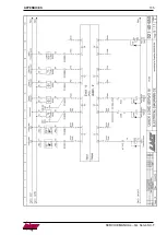
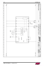
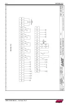
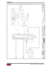
Страница 122: ...APPENDICES 121 SERVICE MANUAL QL Servo S3 T WIRING DIAGRAM 021 40 620F CE MRJ 4 ...

Страница 123: ...122 APPENDICES SERVICE MANUAL QL Servo S3 T ...

Страница 124: ...APPENDICES 123 SERVICE MANUAL QL Servo S3 T ...

Страница 125: ...124 APPENDICES SERVICE MANUAL QL Servo S3 T ...

Страница 126: ...APPENDICES 125 SERVICE MANUAL QL Servo S3 T ...

Страница 127: ...126 APPENDICES SERVICE MANUAL QL Servo S3 T ...

Страница 128: ...APPENDICES 127 SERVICE MANUAL QL Servo S3 T ...

Страница 129: ...128 APPENDICES SERVICE MANUAL QL Servo S3 T ...

Страница 130: ...APPENDICES 129 SERVICE MANUAL QL Servo S3 T ...

Страница 131: ...130 APPENDICES SERVICE MANUAL QL Servo S3 T ...

Страница 132: ...APPENDICES 131 SERVICE MANUAL QL Servo S3 T WIRING DIAGRAM 021 40 650F CE DCS MRJ4 ...

Страница 133: ...132 APPENDICES SERVICE MANUAL QL Servo S3 T ...

Страница 134: ...APPENDICES 133 SERVICE MANUAL QL Servo S3 T ...

Страница 135: ...134 APPENDICES SERVICE MANUAL QL Servo S3 T ...

Страница 136: ...APPENDICES 135 SERVICE MANUAL QL Servo S3 T ...

Страница 137: ...136 APPENDICES SERVICE MANUAL QL Servo S3 T ...

Страница 138: ...APPENDICES 137 SERVICE MANUAL QL Servo S3 T ...

Страница 139: ...138 APPENDICES SERVICE MANUAL QL Servo S3 T ...

Страница 140: ...APPENDICES 139 SERVICE MANUAL QL Servo S3 T ...

Страница 141: ...140 APPENDICES SERVICE MANUAL QL Servo S3 T ...

Страница 142: ...APPENDICES 141 SERVICE MANUAL QL Servo S3 T ...

Страница 143: ...142 APPENDICES SERVICE MANUAL QL Servo S3 T WIRING DIAGRAM 021 40 622C CE MRJ4 QLSIII MI ...

Страница 144: ...APPENDICES 143 SERVICE MANUAL QL Servo S3 T ...

Страница 145: ...144 APPENDICES SERVICE MANUAL QL Servo S3 T ...

Страница 146: ...APPENDICES 145 SERVICE MANUAL QL Servo S3 T ...

Страница 147: ...146 APPENDICES SERVICE MANUAL QL Servo S3 T ...

Страница 148: ...APPENDICES 147 SERVICE MANUAL QL Servo S3 T ...

Страница 149: ...148 APPENDICES SERVICE MANUAL QL Servo S3 T ...

Страница 150: ...APPENDICES 149 SERVICE MANUAL QL Servo S3 T ...

Страница 151: ...150 APPENDICES SERVICE MANUAL QL Servo S3 T PNEUMATIC DIAGRAM ...

Страница 152: ...rm fill it out in its entirety and send it back to your nearest LNS reseller or retailer Company name Person in charge Address ZIP City Country Phone Fax Type of device Serial number Qty Ordering no Description Expected delivery Location and date Signature and stamp of the company ...

Отзывы: