background image

– 21 –

SECTION IX - START UP

A.  Control Checks

1.   On units with PNEUMATIC CONTROLS, take all 

air pressure off. Dampers should go to full face 

open position. Application of full air pressure will 

close the dampers in the opposite direction. Adjust 

the thermostat setting to be sure that when the 

thermostat is calling for heat, the face opens and 

the by-pass closes.

2.   On units with electric controls, follow control 

manufacturer’s instructions for shorting out 

thermostat contacts to move the damper to close 

the face one way, and then the by-pass. Adjust 

thermostat setting to be sure operation is correct 

so that when thermostat is calling for heat, the 

face opens and the by-pass closes.

NOTE:  On electric control units, since motors are 

not spring return, dampers will remain in their last 

operating position if the power is turned off.

B.  Turning Steam On Unit 

(Be sure lower header shipping bolts are removed)

1.   Open all valves on return lines, including trap 

valves and by-pass line around trap, to insure full 

flow of condensate and steam from the coil.

2.   Open all valves in drip trap line from steam main 

before the coil to remove condensate and insure 

dry steam in the main.

3.   Open steam supply line to coil and blow through 

coil with steam to purge coil of air and condensate.

4.   Feel tube surfaces to assure even heating of all 

surfaces before starting fans or opening outside 

shutoff dampers.

5.   Allow unit to “heat soak” at least 15 minutes as in 

step #4.

6.   Open dampers on the heating surface all the way 

by adjusting thermostats or control air pressure to 

units.

7.   Open outside dampers.

8.   Check coil surface for even heating as in step #4.

9.   Slowly close by-pass around traps and check for 

trap operation.

10.  Adjust thermostat or control air pressure to normal 

operating condition and start fan.

11.  Set thermostat for desired temperature. Dampers 

should position to produce required temperature 

rise. Check traps for proper operation.

C.  Turning Hot Water On Unit  

(Be sure lower header(s) shipping bolts are removed)

1.   Open return valve and supply valve.  Purge all air 

from coil and lines.

2.   Feel surface to make sure unit is heating evenly 

and that all air is purged from the coils.

3.   Allow unit to “soak” for at least 10 minutes before 

turning fan on.

4.   Open outside air dampers and start fan.

5.   Feel surface again to check for even heating as in 

step #2.

6.   Adjust balancing valve for desired GPM flow 

through coil.

7.  Set thermostat for desired temperature.  Dampers 

should position to produce required temperature 

rise.

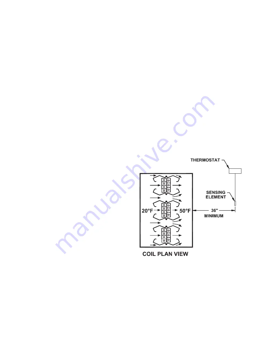
Figure 12 - Thermostat Location (C000677A)

Содержание MV

Страница 1: ...ELS SAVE THIS MANUAL ATTENTION READ THIS MANUAL AND ALL LABELS ATTACHED TO THE UNIT CAREFULLY BEFORE ATTEMPTING TO INSTALL OPERATE OR SERVICE THESE UNITS CHECK UNIT DATA PLATE FOR STEAM OR HOT WATER REQUIREMENTS AND ELECTRICAL SPECIFICATIONS AND MAKE CERTAIN THAT THESE AGREE WITH THOSE AT POINT OF INSTALLATION RECORD THE UNIT MODEL AND SE RIAL No s IN THE SPACE PROVIDED RETAIN FOR FUTURE REFERENCE...

Страница 2: ...ipment require no additional conduit or wire for field reassembly All wire leads will be tagged for ease of reconnection in the field Shipments are made F O B Dallas Texas The unit is securely strapped tied and blocked to prevent shipping damage All shipments are checked by an inspector before they are accepted by the carrier Parts that are shipped unmounted are noted on the bill of lading These p...

Страница 3: ...mounting bracket to prevent damage to the header and tubes during shipment See Figure 1 Shipping bolts must be removed before applying steam or hot water but after all piping connections are made Failure to do so will void factory warranty Figure 1 Shipping Bolt Locations C 000703 F Remove shipping braces before attaching ductwork G Ductwork can be attached to the coil flanges or the coil can stan...

Страница 4: ...nate airflow over the supply and return headers by installing sheet metal isolation plates on the top and bottom upstream of the coils b Inlet and outlet mains should be fully insulated c To eliminate coil temperature override use slow acting on off valves to close at desired set points d The installation of humidifiers with steam manifolds internal of an air handler may provide a temperature over...

Страница 5: ...e coil resulting in poor downstream temperature control B Turning vanes must be used to assure even distribution of air over the entire coil where elbows are used in the inlet and or outlet side of a preheat coil See Figure 6 C When the coil is used as a preheat coil in conjunction with a cooling coil located downstream of the heating coil a minimum space of 36 should be allowed between this coil ...

Страница 6: ... 6 SECTION V EQUIPMENT PHOTOS Photo of Indirect Coupled VIFB Entering Air Side Photo of Indirect Coupled VIFB Leaving Air Side ...

Страница 7: ... 7 Photo of Direct Coupled VIFB Entering Air Side Photo of Direct Coupled VIFB Leaving Air Side ...

Страница 8: ... 8 SECTION VI PARTS DRAWING Enlarged View C Section A A Section D D Elevation ...

Страница 9: ...ing Bar 8 Side Panel 9 Snap Bushing 10 Return Header 11 Casing Support Channel 12 Optional Weather Proof Control Housing 13 Drive Assembly 14 Top and Bottom Panel 15 Bearing Nylon 16 Washer Special 17 Finned 5 8 Tube 18 Damper 19 Washer 1 O D 20 Palnut Fastener 21 Plain Washer 3 16 22 Rivet Brass 23 Damper Rod 24 Bearing Nylon 25 Washer 1 2 26 Retaining Clip 27 Shipping Bolts to be removed before ...

Страница 10: ...corporate a flexible connector to provide for at least 3 8 tube expansion and contraction and to allow the return header to float The integrity of the system depends in part on proper piping The following recommendations should be diligently observed Steam Systems 1 All piping in contact with airflow or inside an air hander should be insulated 2 Install casing level tubes must be vertical 3 Full s...

Страница 11: ... 11 STEAM PIPING VIFB Coil Piping Diagram 15 psig and below W12A ...

Страница 12: ... 12 STEAM PIPING VIFB Coil Piping Diagram Above 15 psig W33B ...

Страница 13: ... 13 HOT WATER PIPING VIFB Coil Piping Diagram One or Three Row Coils W13B ...

Страница 14: ... 14 HOT WATER PIPING VIFB Coil Piping Diagram Two Row Coil W32B ...

Страница 15: ... 15 STEAM PIPING MV Coil Piping Diagram 15 psig and below W27A ...

Страница 16: ... 16 STEAM PIPING MV Coil Piping Diagram Above 15 psig W28A ...

Страница 17: ... 17 HOT WATER PIPING MV Coil Piping Diagram Two Row Coil W29A ...

Страница 18: ...cated in the downstream ductwork a minimum of 3 ft away from the coil The thermostat element must be positioned across both face and by pass sections of the coil parallel to the header C Control installation instructions including diagrams are enclosed in the instruction envelope when special controls and control arrangements are ordered Typical electric and pneumatic control arrangements are indi...

Страница 19: ... 19 ELECTRIC AND PNEUMATIC CONTROLS D000756A ...

Страница 20: ...hten ball joints one on each arm connecting scissor saddle base pan arms to damper lever arm 7 With assembly now set release clamps and rotate damper lever arm until it reaches a point 1 1 2 from casing and clamp in this position Photo 3 8 Manually check to make sure that all dampers are fully closed around the coil 9 Tighten ball joints two on each side connecting base assembly to dampers 10 Remo...

Страница 21: ...3 Open steam supply line to coil and blow through coil with steam to purge coil of air and condensate 4 Feel tube surfaces to assure even heating of all surfaces before starting fans or opening outside shutoff dampers 5 Allow unit to heat soak at least 15 minutes as in step 4 6 Open dampers on the heating surface all the way by adjusting thermostats or control air pressure to units 7 Open outside ...

Страница 22: ...its and allow water to drain E Do not expose a coil which has been shut down to sub freezing air flow as water droplets in tubes may freeze resulting in coil freeze up when coil is restarted See starting instructions SECTION XI MAINTENANCE A The Wing heating coil should be periodically inspected for continuous satisfactory operation Loose nuts bolts screws and damper linkage should be tightened Cr...

Страница 23: ... 23 ...

Страница 24: ...4830 TRANSPORT DRIVE DALLAS TX 75247 TEL 214 638 6010 www ljwing com ...

Отзывы: