


229
Section 1: there are six function buttons: Live
(
chapter 0
)
, setup (chapter 5.8), info (Chapter 5.9),
playback (chapter 5.10), alarm (chapter 5.11), and logout (chapter 5.12).
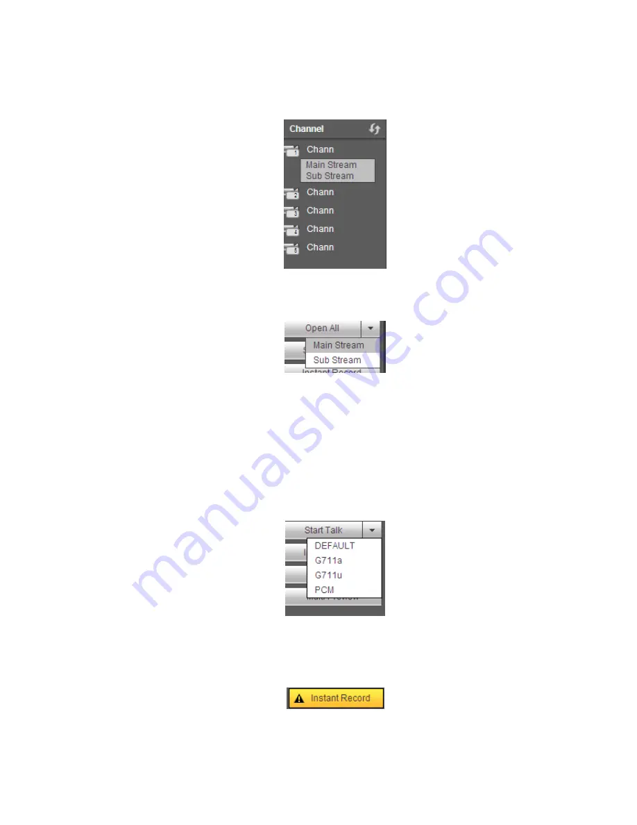
Section 2: There are monitor channels successfully connected to the NVR.
Please refer to Figure 5-4 for main stream and extra stream switch information.
Figure 5-4
Section 3: Open all. Open all button is to enable/disable all-channel real-time monitor. Here you can
select main stream/sub stream too. See Figure 5-5.
Figure 5-5
Section 4: Start Talk button.
You can click this button to enable audio talk. Click
【
▼
】
to select bidirectional talk mode. There are four
options: DEFAULT
,
G711a
,
G711u and PCM. See Figure 5-6.
After you enable the bidirectional talk, the Start talk button becomes End Talk button and it becomes
yellow. Please note, if audio input port from the device to the client-end is using the first channel audio
input port. During the bidirectional talk process, system will not encode the audio data from the 1-channel.
Figure 5-6
Section 5: Instant record button. Click it, the button becomes yellow and system begins manual
record. See Figure 5-7. Click it again, system restores previous record mode.
Figure 5-7
Section 6: Local play button.
Содержание NVR4104W
Страница 1: ...Network Video Recorder User s Manual V 1 8 0...
Страница 41: ...29 Weight 1 5kg 2 5kg Exclude HDD Installation Desk installation...
Страница 105: ...93 Figure 3 4 3 5 5 NVR42 4K Series Please refer to Figure 3 5 for connection sample Figure 3 5...
Страница 111: ...99 Figure 3 12 3 5 13 NVR78 Series Please refer to Figure 3 13 for connection sample...
Страница 112: ...100 Figure 3 13 3 5 14 NVR78 16P Series Please refer to Figure 3 14 for connection sample...
Страница 113: ...101 Figure 3 14 3 5 15 NVR78 RH Series Please refer to Figure 3 15 for connection sample...
Страница 114: ...102 Figure 3 15 3 5 16 NVR70 Series Please refer to Figure 3 16 for connection sample...
Страница 115: ...103 Figure 3 16 3 5 17 NVR70 R Series Please refer to Figure 3 17 for connection sample...
Страница 116: ...104 Figure 3 17 3 5 18 NVR42V 8P Series Please refer to Figure 3 18 for connection sample...
Страница 117: ...105 Figure 3 18...
Страница 176: ...164 Figure 4 81 Figure 4 82...
Страница 177: ...165 Figure 4 83 Figure 4 84...
Страница 183: ...171 Figure 4 89 Figure 4 90...
Страница 184: ...172 Figure 4 91 Figure 4 92...
Страница 185: ...173 Figure 4 93 Figure 4 94...
Страница 187: ...175 Figure 4 96 Figure 4 97...
Страница 213: ...201 Figure 4 125 In Figure 4 125 click one HDD item the S M A R T interface is shown as in Figure 4 126 Figure 4 126...
Страница 274: ...262 The motion detect interface is shown as in Figure 5 54 Figure 5 54 Figure 5 55...
Страница 275: ...263 Figure 5 56 Figure 5 57 Figure 5 58...
Страница 279: ...267 Figure 5 62 Figure 5 63...
Страница 323: ...311...