


166
Figure 4-85
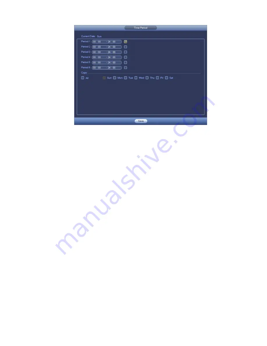
Motion detect here only has relationship with the sensitivity and region setup. It has no relationship
with other setups.
4.11.1.2 Tampering
When someone viciously masks the lens, or the output video is in one -color due to the environments
light change, the system can alert you to guarantee video continuity. Tampering interface is shown as
in Figure 4-86
. You can enable “Alarm output “or “Show message” function when tampering alarm
occurs.
Sensitivity: The value ranges from 1 to 6. It mainly concerns the brightness. The level 6 has the
higher sensitivity than level 1. The default setup is 3.
Tips:
You can enable preset/tour/pattern activation operation when video loss occurs.
Please refer to chapter 4.11.1.1 motion detection for detailed information.
Note:
In Detect interface, copy/paste function is only valid for the same type, which means you can not
copy a channel setup in video loss mode to tampering mode.
About Default function. Since detection channel and detection type may not be the same, system
can only restore default setup of current detect type. For example, if you click Default button at
the tampering interface, you can only restore default tampering setup. It is null for other detect
types.
System only enables tampering function during the period you set here. It is null for motion detect
or video loss type.
Содержание NVR4104W
Страница 1: ...Network Video Recorder User s Manual V 1 8 0...
Страница 41: ...29 Weight 1 5kg 2 5kg Exclude HDD Installation Desk installation...
Страница 105: ...93 Figure 3 4 3 5 5 NVR42 4K Series Please refer to Figure 3 5 for connection sample Figure 3 5...
Страница 111: ...99 Figure 3 12 3 5 13 NVR78 Series Please refer to Figure 3 13 for connection sample...
Страница 112: ...100 Figure 3 13 3 5 14 NVR78 16P Series Please refer to Figure 3 14 for connection sample...
Страница 113: ...101 Figure 3 14 3 5 15 NVR78 RH Series Please refer to Figure 3 15 for connection sample...
Страница 114: ...102 Figure 3 15 3 5 16 NVR70 Series Please refer to Figure 3 16 for connection sample...
Страница 115: ...103 Figure 3 16 3 5 17 NVR70 R Series Please refer to Figure 3 17 for connection sample...
Страница 116: ...104 Figure 3 17 3 5 18 NVR42V 8P Series Please refer to Figure 3 18 for connection sample...
Страница 117: ...105 Figure 3 18...
Страница 176: ...164 Figure 4 81 Figure 4 82...
Страница 177: ...165 Figure 4 83 Figure 4 84...
Страница 183: ...171 Figure 4 89 Figure 4 90...
Страница 184: ...172 Figure 4 91 Figure 4 92...
Страница 185: ...173 Figure 4 93 Figure 4 94...
Страница 187: ...175 Figure 4 96 Figure 4 97...
Страница 213: ...201 Figure 4 125 In Figure 4 125 click one HDD item the S M A R T interface is shown as in Figure 4 126 Figure 4 126...
Страница 274: ...262 The motion detect interface is shown as in Figure 5 54 Figure 5 54 Figure 5 55...
Страница 275: ...263 Figure 5 56 Figure 5 57 Figure 5 58...
Страница 279: ...267 Figure 5 62 Figure 5 63...
Страница 323: ...311...