


127
VGA+HDMI2: It is for dual-screen operation. Please select from the dropdown list according to your
actual situation. Click Apply button, system needs to restart to activate new setup. For example,
32+4 means for VGA, system max supports 32-window split and for HDMI2, system max supports
4-window split.
Transparency: Here is for you to adjust transparency. The value ranges from 128 to 255.
Channel name: Here is for you to modify channel name. System max support 25-digit (The value
may vary due to different series). Please note all your modification here only applies to NVR local
end. You need to open web or client end to refresh channel name.
Time display: You can select to display time or not when system is playback.
Channel display: You can select to channel name or not when system is playback.
Image enhance: Check the box; you can optimize the margin of the preview video.
Original scale: Check the box here to restore video original scale.
Click OK button to save current setup.
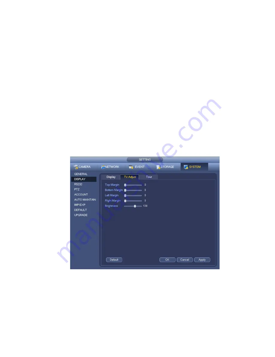
4.6.4.3 TV adjust
Note
Some series product supports TV adjust function.
From Main Menu->Setting->System->Display->TV adjust; you can go to the following interface. See
Figure 4-33. Here you can set margins and brightness.
Figure 4-34
4.6.5
Preview Tour Parameters
Set preview display mode, channel display sequence and tour setup.
Set preview display mode: On the preview interface, right click mouse, you can view right-click menu.
Now you can select preview window amount and channel.
Set channel display mode: On the preview interface, if you want to change channel 1 and channel 16
Содержание NVR4104W
Страница 1: ...Network Video Recorder User s Manual V 1 8 0...
Страница 41: ...29 Weight 1 5kg 2 5kg Exclude HDD Installation Desk installation...
Страница 105: ...93 Figure 3 4 3 5 5 NVR42 4K Series Please refer to Figure 3 5 for connection sample Figure 3 5...
Страница 111: ...99 Figure 3 12 3 5 13 NVR78 Series Please refer to Figure 3 13 for connection sample...
Страница 112: ...100 Figure 3 13 3 5 14 NVR78 16P Series Please refer to Figure 3 14 for connection sample...
Страница 113: ...101 Figure 3 14 3 5 15 NVR78 RH Series Please refer to Figure 3 15 for connection sample...
Страница 114: ...102 Figure 3 15 3 5 16 NVR70 Series Please refer to Figure 3 16 for connection sample...
Страница 115: ...103 Figure 3 16 3 5 17 NVR70 R Series Please refer to Figure 3 17 for connection sample...
Страница 116: ...104 Figure 3 17 3 5 18 NVR42V 8P Series Please refer to Figure 3 18 for connection sample...
Страница 117: ...105 Figure 3 18...
Страница 176: ...164 Figure 4 81 Figure 4 82...
Страница 177: ...165 Figure 4 83 Figure 4 84...
Страница 183: ...171 Figure 4 89 Figure 4 90...
Страница 184: ...172 Figure 4 91 Figure 4 92...
Страница 185: ...173 Figure 4 93 Figure 4 94...
Страница 187: ...175 Figure 4 96 Figure 4 97...
Страница 213: ...201 Figure 4 125 In Figure 4 125 click one HDD item the S M A R T interface is shown as in Figure 4 126 Figure 4 126...
Страница 274: ...262 The motion detect interface is shown as in Figure 5 54 Figure 5 54 Figure 5 55...
Страница 275: ...263 Figure 5 56 Figure 5 57 Figure 5 58...
Страница 279: ...267 Figure 5 62 Figure 5 63...
Страница 323: ...311...