


135
Call Scan
In Figure 4-41, input Scan value and then click
to call a tour. Click again
to stop call.
Rotate
In Figure 4-41, click
to enable the camera to rotate.
System supports preset, tour, pattern, scan, rotate, light and etc function.
Note:
Preset, tour and pattern all need the value to be the control parameters. You can define it as y ou
require.
You need to refer to your camera user’s manual for Aux definition. In some cases, it can be used for
special process.
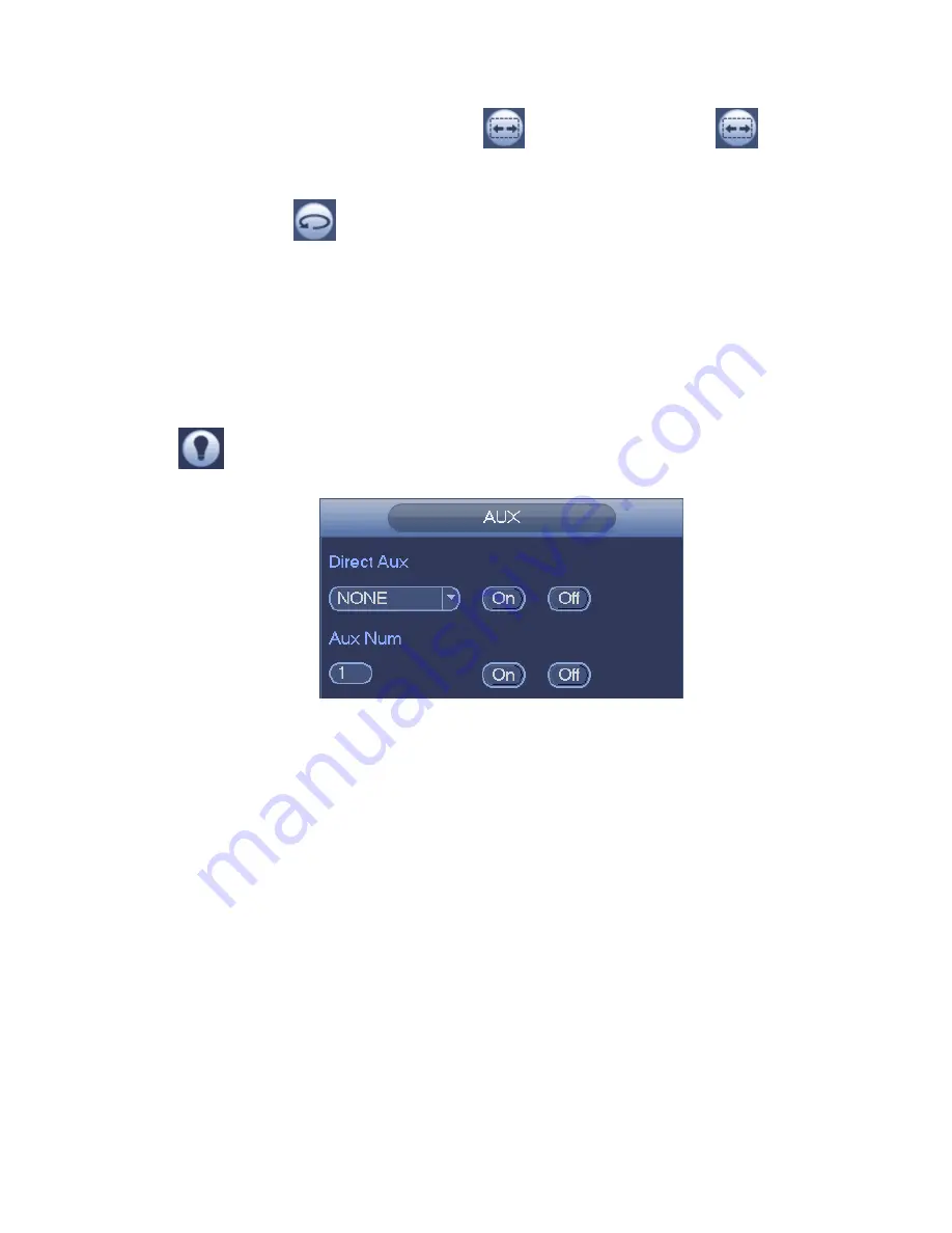
Aux
Click
, system goes to the following interface. The options here are defined by the protocol. The aux
number is corresponding to the aux on-off button of the decoder. See Figure 4-47.
Figure 4-47
4.8 Record and Snapshot
The record/snapshot priority is: Alarm->Motion detect->Schedule.
4.8.1
Encode
4.8.1.1 Encode
Encode setting is to set IPC encode mode, resolution, bit stream type and etc
From Main menu->Setting->System->Encode, you can see the following interface. See Figure 4-48.
Channel: Select the channel you want.
Type: Please select from the dropdown list. There are three options: regular/motion detect/alarm.
You can set the various encode parameters for different record types.
Compression: System supports H.264, MPEG4, MJPEG and etc.
Resolution: The
mainstream resolution type is IPC’s encoding config. Generally there is
D1/720P/1080P. For NVR42-4K, NVR42-8P-4K series product, the main stream supports 2048
×
1536
(
3M
)
,1920
×
1080
(
1080P
)
, 1280
×
1024
(
S
×
GA
)
, 1280
×
960
(
1.3M
)
,1280
×
720
(
720P
)
,704
×
576
(
D1
)
and the sub stream supports 704
×
576
(
D1
)
,352
×
288
(
CIF
)
.
Содержание NVR4104W
Страница 1: ...Network Video Recorder User s Manual V 1 8 0...
Страница 41: ...29 Weight 1 5kg 2 5kg Exclude HDD Installation Desk installation...
Страница 105: ...93 Figure 3 4 3 5 5 NVR42 4K Series Please refer to Figure 3 5 for connection sample Figure 3 5...
Страница 111: ...99 Figure 3 12 3 5 13 NVR78 Series Please refer to Figure 3 13 for connection sample...
Страница 112: ...100 Figure 3 13 3 5 14 NVR78 16P Series Please refer to Figure 3 14 for connection sample...
Страница 113: ...101 Figure 3 14 3 5 15 NVR78 RH Series Please refer to Figure 3 15 for connection sample...
Страница 114: ...102 Figure 3 15 3 5 16 NVR70 Series Please refer to Figure 3 16 for connection sample...
Страница 115: ...103 Figure 3 16 3 5 17 NVR70 R Series Please refer to Figure 3 17 for connection sample...
Страница 116: ...104 Figure 3 17 3 5 18 NVR42V 8P Series Please refer to Figure 3 18 for connection sample...
Страница 117: ...105 Figure 3 18...
Страница 176: ...164 Figure 4 81 Figure 4 82...
Страница 177: ...165 Figure 4 83 Figure 4 84...
Страница 183: ...171 Figure 4 89 Figure 4 90...
Страница 184: ...172 Figure 4 91 Figure 4 92...
Страница 185: ...173 Figure 4 93 Figure 4 94...
Страница 187: ...175 Figure 4 96 Figure 4 97...
Страница 213: ...201 Figure 4 125 In Figure 4 125 click one HDD item the S M A R T interface is shown as in Figure 4 126 Figure 4 126...
Страница 274: ...262 The motion detect interface is shown as in Figure 5 54 Figure 5 54 Figure 5 55...
Страница 275: ...263 Figure 5 56 Figure 5 57 Figure 5 58...
Страница 279: ...267 Figure 5 62 Figure 5 63...
Страница 323: ...311...