


128
position, please right click channel 1 video window and then drag to the channel 16 video window,
release button, you can change channel 1 and channel 16 position.
Tour setup: Here you can set preview window channel display mode and interval. Please follow the
steps listed below.
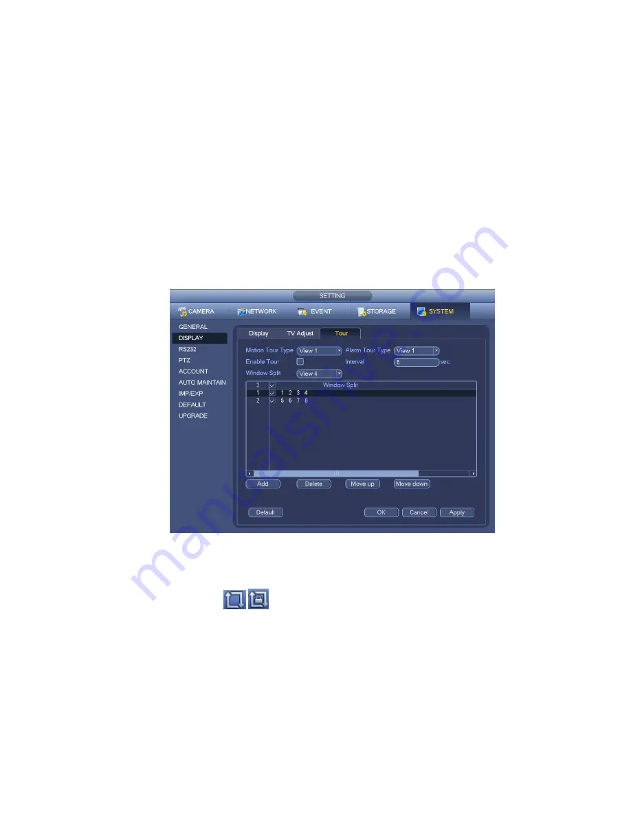
From Main menu->Setting->System->Display->Tour, you can see an interface shown as in Figure 4-35.
Here you can set tour parameter.
Enable tour: Check the box here to enable tour function.The general tour supports all types of
window split mode.
Interval: Input proper interval value here. The value ranges from 1-120 seconds.
Motion tour type: System support 1/8-window tour. Please note you need to go to the main
menu->Setting->Event->Video detect->Motion detect to enable tour function.
Alarm tour type: System support 1/8-window tour. Please note you need to go to the main
menu->Setting->Event->Alarm to enable tour function.
Window split:It is to set window split mode.
Figure 4-35
Tips
On the navigation bar, click
/
to enable/disable tour.
Click Save button to save current setup.
4.7 PTZ
Note:
Before you control the PTZ, please make sure the PTZ decoder and the NVR network
connection is OK and the corresponding settings are right.
4.7.1
PTZ Settings
Cable Connection
Содержание NVR4104W
Страница 1: ...Network Video Recorder User s Manual V 1 8 0...
Страница 41: ...29 Weight 1 5kg 2 5kg Exclude HDD Installation Desk installation...
Страница 105: ...93 Figure 3 4 3 5 5 NVR42 4K Series Please refer to Figure 3 5 for connection sample Figure 3 5...
Страница 111: ...99 Figure 3 12 3 5 13 NVR78 Series Please refer to Figure 3 13 for connection sample...
Страница 112: ...100 Figure 3 13 3 5 14 NVR78 16P Series Please refer to Figure 3 14 for connection sample...
Страница 113: ...101 Figure 3 14 3 5 15 NVR78 RH Series Please refer to Figure 3 15 for connection sample...
Страница 114: ...102 Figure 3 15 3 5 16 NVR70 Series Please refer to Figure 3 16 for connection sample...
Страница 115: ...103 Figure 3 16 3 5 17 NVR70 R Series Please refer to Figure 3 17 for connection sample...
Страница 116: ...104 Figure 3 17 3 5 18 NVR42V 8P Series Please refer to Figure 3 18 for connection sample...
Страница 117: ...105 Figure 3 18...
Страница 176: ...164 Figure 4 81 Figure 4 82...
Страница 177: ...165 Figure 4 83 Figure 4 84...
Страница 183: ...171 Figure 4 89 Figure 4 90...
Страница 184: ...172 Figure 4 91 Figure 4 92...
Страница 185: ...173 Figure 4 93 Figure 4 94...
Страница 187: ...175 Figure 4 96 Figure 4 97...
Страница 213: ...201 Figure 4 125 In Figure 4 125 click one HDD item the S M A R T interface is shown as in Figure 4 126 Figure 4 126...
Страница 274: ...262 The motion detect interface is shown as in Figure 5 54 Figure 5 54 Figure 5 55...
Страница 275: ...263 Figure 5 56 Figure 5 57 Figure 5 58...
Страница 279: ...267 Figure 5 62 Figure 5 63...
Страница 323: ...311...