CPU Switch Smart DVI
Installation and Use
Page 8
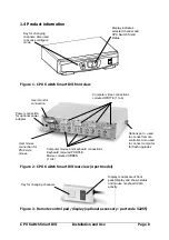
1.4 Product information
Figure 1 - CPU Switch Smart DVI front view
Figure 2 - CPU Switch Smart DVI rear view (4 port model)
Figure 3 - Remote control pad / display (optional accessory - part code 32255)
Key for changing
channels. Also used
to access configure
mode
Display indicates
selected channel and
CPU Switch Smart
status
User monitor
connection
Power connection
for optional power
adapter
User mouse
connection for
PS/2 style
mouse
Computer video connections
coloured WHITE (1 to 4)
Computer mouse and keyboard connections
Keyboard coloured PURPLE
Mouse coloured GREEN
(1 to4)
Key for changing channels
Options port – used
to connect remote
controller. Also used
to connect computer
for flash upgrades
Display is duplicate of front
panel display and shows status
and mouse / keyboard data
activity


