


23
The covering of this variable restrictor
D
3
is the result of the
equilibrium of the pressures
p
1
and
p
2
and of the spring force
F
on the control piston. The influence of viscosity is only slight,
due to the relatively short hydraulic length which arises from
the geometry of the plug-in nozzles
D
1
or
D
1
/
D
2
, respectively.
The flow rate is thus determined only by the differential
pressure
p
1/2
, which is constant. This results in the flow rate
also being constant.
p1*A = p2*A + F (A = cross-sectional area of the control
piston)
Δp = p1/2 = p1 – p2 = F/A = const.
Δp = const.
Q = const. 1)
Prerequisites
To ensure impeccable functioning of the flow limiter,
p
1
must
always be greater than the differential pressure
p
1/2
plus the
back pressure downstream of the flow limiter.
p
1
>
p
1/2
+
p
3
We recommend that a reserve of approximately 15% be
provided for the selection of the oil pump.
Q
pump
≥ 1.15 * ΣQ
in
Circulating-oil lubrication systems with flow limiters,
which are
equipped with downstream progressive metering devices
are
usually run with a system pressure of 20-25 bar (290-360 psi),
while a system pressure of 16 bar (230 psi) is sufficient for
systems comprised solely of flow limiters.
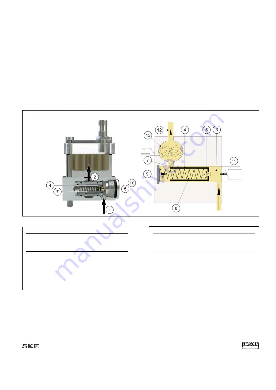
Fig. 6
Functional diagram SMBM-X
Table 7
Legend to Fig. 6
Item Designation
1
Inlet volume flow
Q
in
2
Outlet volumetric flow
Q
out
3 Inlet
pressure
p
1
upstream of
D
1
4 Control
piston
SK
5 Plug-in
nozzle
D
1
(nonadjustable restrictor)
7 Variable
restrictor
D
3
8 Inner
pressure
p
2
downstream of
D
1
Table 7
Legend to Fig. 6
Item Designation
9 Spring
force
F
10 Stop
screw
AS
11 Signal
transmitter
SG
(optional)
12
Outlet pressure
p
3
downstream of
D
2
(back
pressure in the system)
13
Gear-type flow indicator with pulse generator
Содержание SKF SMBM-V EEX
Страница 49: ...49 Fig 32 Mechanical connection options SMBM V...
Страница 61: ...61 Fig 40 Replacement of an SMBM module...
Страница 62: ...62 Fig 41 Expansion of an existing assembly to include an SMBM module...
Страница 73: ...73...


