


2
1.2 DESCRIPTION
The inlet and outlet threads are Class B, 9/16”-18 (M) (LH) for fuel gas and (RH) for oxygen, CGA 032, Class “B” 5/8”-18 (F) (RH) and 1/4” NPT (M) for inert gas.
(See Table A.).
The Gas Block shut-off valves can be individually adjusted using their seat adjustment screws and lock nuts (Ref. __).
(See 3.4 SHUT-OFF VALVE ADJUSTMENT.) Both Gas Block hanger rods can also be adjusted according to the weight of the torch equipment being used. (See 3.3
HANGER ROD ADJUSTMENT.)
TABLE A
- Inlet and outlet connections for Harris Gas Block
P/N
Gas
Inlet
Outlet
4300943
Oxygen
CGA 022 Class “B” 9/16”-18 RH (M) CGA 022 Class “B” 9/16”-18 RH (M)
Fuel
CGA 023 Class “B” 9/16”-18 LH (M) CGA 023 Class “B” 9/16”-18 LH (M)
4300944
Oxygen
CGA 022 Class “B” 9/16”-18 RH (M) CGA 022 Class “B” 9/16”-18 RH (M)
Fuel
CGA 023 Class “B” 9/16”-18 LH (M) CGA 023 Class “B” 9/16”-18 LH (M)
Inert Gas
CGA 032 Class “B” 5/8”-18 RH (F)
1/4” NPT (M)
2. INSTALLATION
The Gas Block is a shut-off unit and not a pressure regulating device. It is intended for installation downstream of the pressure regulators.
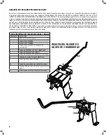
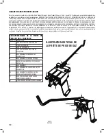
A. Secure the Gas Block on a bench, or other horizontal surface, using the four to six mounting holes in the Gas Block Base
(Item 1 TABLE B)
. Position the Gas
Block so that when the torch is placed on the hanger rod, the torch flame will point away from the operator and not in the proximity of any combustible material;
also, so that the bench or surface does not contact the hoses and restrict gas flow downstream.
The Gas Block is shipped with the hanger rod
(Item 2 TABLE B)
packed separately, but in the same carton as the main body. Insert the rod, straight end, into
the hole in the hanger block
(Item 3 TABLE B)
on the side of Gas Block marked “OUTLET.” Push rod through hanger block hole on opposite side and allow it to
protrude about three (3) inches. Tighten hanger rod lock screw
(Item 4 TABLE B)
.
B. Connect the fuel gas hose from the regulator (grooved nut) to the connection marked “INLET (LH)”
(Item 5 TABLE B)
and the oxygen hose from the regulator
(non-grooved nut) to the connection marked “INLET (RH)”
(Item 6 TABLE B).
Connect inert gas supply to inert gas inlet
(Item 7 TABLE B)
, if so equipped.
C. Connect torch hoses to the respective Gas Block outlets. Fuel gas hose (grooved nut) to “OUTLET (LH)”
(Item 8 TABLE B)
and oxygen hose (non-grooved nut) to
“OUTLET (RH)”
(Item 9 TABLE B).
Connect torch to outlet hoses. Connect inert gas outlet hose to inert gas outlet connection
(Item 10 TABLE B)
.
D. To close Gas Block valves, place oxy-fuel or air-fuel torch on Gas Block hanger rod.
E. Open cylinder or pipeline valves pressurizing the system. Adjust regulators to the operating pressures recommended by the torch equipment manufacturer.*
Before lifting torch from hanger rod, make sure torch valves, if so equipped, are fully closed. Lift torch from hanger rod and test torch for leaks. Do not proceed
until all leaks are corrected and torch is returned to hanger rod.
F. Purge gas system. Lift torch from hanger rod and open then close each torch valve* independently. Recommended purge time is 5 seconds for every 10 feet of
hose. Purging oxy-fuel system is recommended to prevent flashbacks due to gases being mixed in the system beyond where intended. Shielding gases in 3 Gas
Blocks can also be purged using the same method.
*Note: If using torches without valves or with valves capped, follow the same purging sequence using the pipeline supply or the cylinder valve(s) to purge and use
upstream regulators to set tip pressures.
3. GENERAL OPERATION
3.1 USE
Torch equipment should be operated according to the manufacturer’s instructions. When the torch operation is completed, place the torch on the hanger rod to
extinguish the flame. For reuse, remove the torch from hanger rod and, without delay, relight torch using an approved ignition source. When the torch will not be
used for an extended period of time, for example, at the end of the work day, close the main supply valve and bleed gas pressure from the regulator, Gas Block,
hoses and torch system.
3.2 PRESSURE SETTINGS
The Gas Block generally does not significantly affect regulator pressure settings for the torch. Use regulator pressure settings recommended by the oxy-fuel torch,
tip and/or mixer manufacturer. Setting pressures in an “at flow” condition is generally recommended especially when using higher volume tips.


