Theory of Operation
74
Firmware
The operator interface enables you to monitor the STS2/PDU, to configure setpoints for transfers,
monitor system parameters and access event and history logs. The firmware is accessible through the
LCD touch screen or the RS-232 interface. The firmware includes:
• View and set the preferred source.
• View and configure setpoints.
• View alarms, faults and status.
• The mimic graphical representation of the systems operation.
• Menu driven monitoring and configuration.
• Step-by-step instructions to assist you in the start-up, shut-down and bypass operations.
• Help on event messages.
• Touch screen alarm reset and silence buttons.
Events in the system, both faults and alarms, are detected and displayed on the LCD. See
11.0 -
Alarms and Faults
for more information on events.
• A set of event masks can be configured through the LCD to trigger a system response to an event.
See
11.1 - Event Mask
.
• Report event conditions from other components of the system.
• Monitor and report changes in event condition states. If the event condition’s state changes from
inactive to active, a new event is detected. If the transition is from active to inactive, the event
condition has cleared.
• Process new faults and alarms and clear inactive alarms.
• Provide the alarm reset and silence options.
9.2.2 Circuit Breakers and Non-Automatic Circuit Breakers
Input circuit breaker for each source provides over current protection for the STS2/PDU. Three non-
automatic circuit breakers provide total isolation of the solid-state switching devices with an input
non-automatic breaker for each source and a load isolation non-automatic breaker. Two non-automatic
breakers provide for maintenance bypassing of the solid-state switching devices to either input source.
All breakers in the STS2/PDU are plug-in types, which allows any breaker to be replaced without de-
energizing the output bus. The breakers have an interlock in the plug-in base, which prevents the
switch from being withdrawn in the CLOSED position. The switch trips OPEN before it disconnects
from the plug-in base.
See
14.2.5 - Circuit Breakers
for specifications and more information pertaining to the circuit
breakers. See
Figures 23
through
36
for circuit breaker locations.
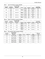
The circuit breaker schedule is provided in
Tables 9
through
11
.
9.2.3 SCRs
Brick-type SCRs are used rated to carry the full 100% rated load. The unit is a fuseless design with
input circuit breakers providing overcurrent protection.
9.2.4 Logic Modules
The logic contains three separate redundant logic modules. The modules contain the logic necessary
to run the STS2/PDU and control transfers and shunt trips under all circumstances, without any out-
side assistance once set-up and started properly.
9.2.5 Audible Alarm
An audible alarm is installed on the control board. This alarm is triggered by an alarm condition
detected on the unit. The alarm can be turned off from the touch screen. Turning off the audible alarm
does not clear or reset the condition that triggered the alarm.
9.2.6 RS-232 Port
An RS-232 serial port is provided to allow an external terminal to be connected as another user inter-
face. See
12.1 - Using the RS-232 Port
for more information.
Содержание PDUTM
Страница 1: ...POWER DISTRIBUTION STS2 PDU INSTALLATION OPERATION MAINTENANCE MANUAL 250A 800A Three Phase 60 Hz ...
Страница 25: ...Installation Drawings 17 7 0 INSTALLATION DRAWINGS Figure 7 Outline drawing 250A STS2 PDU ...
Страница 26: ...Installation Drawings 18 Figure 8 Outline drawing 250A STS2 PDU with right side I Line distribution ...
Страница 27: ...Installation Drawings 19 Figure 9 Outline drawing 250A STS2 PDU with right side inline distribution ...
Страница 28: ...Installation Drawings 20 Figure 10 Outline drawing 250A STS2 PDU with left side I Line distribution ...
Страница 29: ...Installation Drawings 21 Figure 11 Outline drawing 250A STS2 PDU with left side Inline distribution ...
Страница 30: ...Installation Drawings 22 Figure 12 Outline drawing 400 600A STS2 PDU with right side inline distribution ...
Страница 32: ...Installation Drawings 24 Figure 14 Outline drawing 400 600A STS2 PDU with left side inline distribution ...
Страница 35: ...Installation Drawings 27 Figure 17 Outline drawing 800A STS2 PDU with right side inline distribution ...
Страница 37: ...Installation Drawings 29 Figure 19 Outline drawing 800A STS2 PDU with left side inline distribution ...
Страница 38: ...Installation Drawings 30 Figure 20 Outline drawing 250A STS2 PDU with key lockout switch option ...
Страница 41: ...Installation Drawings 33 Figure 23 Electrical field connections 250A STS2 PDU input output with CB8 ...
Страница 42: ...Installation Drawings 34 Figure 24 Electrical field connections 250A STS2 PDU input with CB3 ...
Страница 43: ...Installation Drawings 35 Figure 25 Electrical field connections 250A STS2 PDU input with CB3 CB3A ...
Страница 44: ...Installation Drawings 36 Figure 26 Electrical field connections 400 600A STS2 PDU input with CB3 ...
Страница 45: ...Installation Drawings 37 Figure 27 Electrical field connections 400 600A STS2 PDU input with CB3 and CB3A ...
Страница 46: ...Installation Drawings 38 Figure 28 Electrical field connections 800A STS2 PDU input with CB3 ...
Страница 47: ...Installation Drawings 39 Figure 29 Electrical field connections 800A STS2 PDU input with CB3 and CB3A ...
Страница 48: ...Installation Drawings 40 Figure 30 Electrical field connections 250A STS2 PDU output with inline panelboards ...
Страница 50: ...Installation Drawings 42 Figure 32 Electrical field connections STS2 PDU output with I Line panelboard ...
Страница 53: ...Installation Drawings 45 Figure 35 Electrical field connections 800A STS2 PDU with right side output breaker ...
Страница 54: ...Installation Drawings 46 Figure 36 Electrical field connections 8600A STS2 PDU with left side output breaker ...
Страница 55: ...Installation Drawings 47 Figure 37 Electrical field connections 800A STS2 PDU interconnect wiring ...
Страница 57: ...Installation Drawings 49 Figure 39 Electrical field connections 800A STS2 PDU interconnect wiring STS section ...
Страница 63: ...Installation Drawings 55 Figure 45 Control wiring 800A STS2 PDU left side distribution ...
Страница 64: ...Installation Drawings 56 Figure 46 Control wiring 800A STS2 PDU right side distribution ...
Страница 65: ...Installation Drawings 57 Figure 47 Control connection location 250A STS2 PDU ...
Страница 66: ...Installation Drawings 58 Figure 48 Control connection location 400 800A STS2 PDU ...
Страница 67: ...Installation Drawings 59 Figure 49 Control location drawing conduit box top entry 400 600A STS2 PDU ...
Страница 68: ...Installation Drawings 60 Figure 50 Control wiring for the programmable relay board option ...
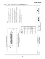
Страница 69: ...Installation Drawings 61 Figure 51 Control wiring for the input contact isolator board option ...
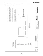
Страница 70: ...Installation Drawings 62 Figure 52 Control wiring for comms board ...
Страница 71: ...Installation Drawings 63 Figure 53 Control wiring for the internal modem option ...
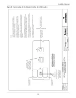
Страница 72: ...Installation Drawings 64 Figure 54 Control wiring for the Network Interface Card NIC option ...
Страница 73: ...Installation Drawings 65 Figure 55 Control wiring for the RS 232 Port ...
Страница 74: ...Installation Drawings 66 Figure 56 Control wiring for remote source selection option ...
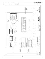
Страница 75: ...Installation Drawings 67 Figure 57 Color LCD touch screen display ...
Страница 155: ......


