Communication Interfaces
94
Putting the Terminal Command Together
For example, a unit only has the Remote Source Selection and Dual-Output Breaker options installed.
Checking the bits list under
Options_1 on page 92
, bits 7 and 0 each must be set to 1 to indicate
that these options are installed.
The bit setting is as follows, starting with bit 15 on the left and going down to bit 0:
0000 0000 1000 0001
With the bits combined in groups of four, the binary settings can be translated into hexadecimal val-
ues.
The first two groups in the sample equal zero (0). In the third group, 1000 in binary translates to 8 in
hex. In the fourth group, 0001 in binary translates to 1 in hex.
In hex, this equates to (digits in the value parameter cannot have spaces between them):
0081
So your command to indicate that the Remote Source Selection and the Dual-Output Breaker are
installed would be:
SPT 2 6 0081
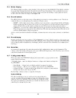
12.1.4 Setting Event Masks with the Terminal
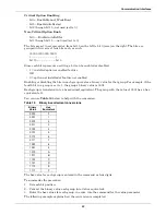
The event masks can be customized via a terminal. The command SPT4?<ENTER> displays all faults
and alarms, along with their associated event masks. A plus sign (+) means that particular event
mask is enabled, while a minus sign (-) means that mask is disabled.
Refer to
11.1 - Event Mask
for more information on event masks and their associated flags.
Unlike the System and User Settings, mask values are set by designated letters, not hex values.
However, as with other RS-232 interface settings, four parameters are passed. See
12.1.2 - Configur-
ing the STS2/PDU via the Terminal
for more details about the parameters.
The syntax for configuring event masks is:
SPT 4 ID ±D±L±S±E±A
• SPT — is the terminal command used to configure setpoints.
• 4 — setting (group parameter) for event masks, under System Settings.
• ID — event ID. The ID is the item parameter for this command. The ID numbers for each event
are listed with the events in
Table 12
.
• D,L,S,E,A — the event masks: Dial, Latch, Summary, Event log and Audible. The masks are the
value parameter for the command.
Each mask type must be preceded by a plus sign (+) to enable it or by a minus sign (-) to disable it.
Only the mask that is passed (enabled) is applied when the event occurs.
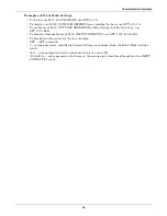
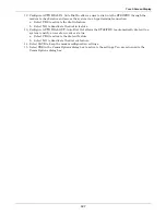
To set the event masks for a particular event:
1. Enter the command. Examples and descriptions are provided below.
2. Press ENTER.
After the new settings are entered, the new results for that event ID are displayed.
NOTE
NO spaces are placed between each mask listed above.
Содержание PDUTM
Страница 1: ...POWER DISTRIBUTION STS2 PDU INSTALLATION OPERATION MAINTENANCE MANUAL 250A 800A Three Phase 60 Hz ...
Страница 25: ...Installation Drawings 17 7 0 INSTALLATION DRAWINGS Figure 7 Outline drawing 250A STS2 PDU ...
Страница 26: ...Installation Drawings 18 Figure 8 Outline drawing 250A STS2 PDU with right side I Line distribution ...
Страница 27: ...Installation Drawings 19 Figure 9 Outline drawing 250A STS2 PDU with right side inline distribution ...
Страница 28: ...Installation Drawings 20 Figure 10 Outline drawing 250A STS2 PDU with left side I Line distribution ...
Страница 29: ...Installation Drawings 21 Figure 11 Outline drawing 250A STS2 PDU with left side Inline distribution ...
Страница 30: ...Installation Drawings 22 Figure 12 Outline drawing 400 600A STS2 PDU with right side inline distribution ...
Страница 32: ...Installation Drawings 24 Figure 14 Outline drawing 400 600A STS2 PDU with left side inline distribution ...
Страница 35: ...Installation Drawings 27 Figure 17 Outline drawing 800A STS2 PDU with right side inline distribution ...
Страница 37: ...Installation Drawings 29 Figure 19 Outline drawing 800A STS2 PDU with left side inline distribution ...
Страница 38: ...Installation Drawings 30 Figure 20 Outline drawing 250A STS2 PDU with key lockout switch option ...
Страница 41: ...Installation Drawings 33 Figure 23 Electrical field connections 250A STS2 PDU input output with CB8 ...
Страница 42: ...Installation Drawings 34 Figure 24 Electrical field connections 250A STS2 PDU input with CB3 ...
Страница 43: ...Installation Drawings 35 Figure 25 Electrical field connections 250A STS2 PDU input with CB3 CB3A ...
Страница 44: ...Installation Drawings 36 Figure 26 Electrical field connections 400 600A STS2 PDU input with CB3 ...
Страница 45: ...Installation Drawings 37 Figure 27 Electrical field connections 400 600A STS2 PDU input with CB3 and CB3A ...
Страница 46: ...Installation Drawings 38 Figure 28 Electrical field connections 800A STS2 PDU input with CB3 ...
Страница 47: ...Installation Drawings 39 Figure 29 Electrical field connections 800A STS2 PDU input with CB3 and CB3A ...
Страница 48: ...Installation Drawings 40 Figure 30 Electrical field connections 250A STS2 PDU output with inline panelboards ...
Страница 50: ...Installation Drawings 42 Figure 32 Electrical field connections STS2 PDU output with I Line panelboard ...
Страница 53: ...Installation Drawings 45 Figure 35 Electrical field connections 800A STS2 PDU with right side output breaker ...
Страница 54: ...Installation Drawings 46 Figure 36 Electrical field connections 8600A STS2 PDU with left side output breaker ...
Страница 55: ...Installation Drawings 47 Figure 37 Electrical field connections 800A STS2 PDU interconnect wiring ...
Страница 57: ...Installation Drawings 49 Figure 39 Electrical field connections 800A STS2 PDU interconnect wiring STS section ...
Страница 63: ...Installation Drawings 55 Figure 45 Control wiring 800A STS2 PDU left side distribution ...
Страница 64: ...Installation Drawings 56 Figure 46 Control wiring 800A STS2 PDU right side distribution ...
Страница 65: ...Installation Drawings 57 Figure 47 Control connection location 250A STS2 PDU ...
Страница 66: ...Installation Drawings 58 Figure 48 Control connection location 400 800A STS2 PDU ...
Страница 67: ...Installation Drawings 59 Figure 49 Control location drawing conduit box top entry 400 600A STS2 PDU ...
Страница 68: ...Installation Drawings 60 Figure 50 Control wiring for the programmable relay board option ...
Страница 69: ...Installation Drawings 61 Figure 51 Control wiring for the input contact isolator board option ...
Страница 70: ...Installation Drawings 62 Figure 52 Control wiring for comms board ...
Страница 71: ...Installation Drawings 63 Figure 53 Control wiring for the internal modem option ...
Страница 72: ...Installation Drawings 64 Figure 54 Control wiring for the Network Interface Card NIC option ...
Страница 73: ...Installation Drawings 65 Figure 55 Control wiring for the RS 232 Port ...
Страница 74: ...Installation Drawings 66 Figure 56 Control wiring for remote source selection option ...
Страница 75: ...Installation Drawings 67 Figure 57 Color LCD touch screen display ...
Страница 155: ......


