Touch Screen Display
102
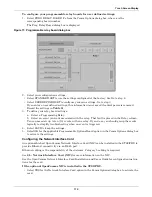
To configure the setpoints for each source:
1. Select SOURCE 1/2 SETPOINTS from the User Settings dialog box. The Source 1/2 Setpoints
dialog is displayed.
Figure 68 Source setpoints
2. Select 1 to configure the settings for Source 1.
3. Configure the settings using the keypad or dialog box that is displayed when you touch a button.
4. Select 2 for Source 2.
5. Configure the settings, as described in step 3.
6. Select SAVE to keep the settings for both sources. The Setpoints dialog is closed and the User
Settings dialog is displayed.
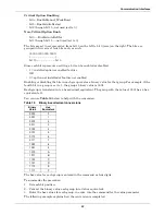
7. Select MANUAL MAX XFER PHASE ANGLE. A keypad is displayed.
This setting configures the maximum allowed phase difference between the sources and applies to
all manual transfers as well as any auto retransfer.
a. Configure this setting with a range of +/- 1-30 degrees. The default setting is +/-15 degrees
and the resolution is 1 deg.
b. Select OK to save the setting. The setting is now displayed in the adjacent field in the User
Settings dialog box.
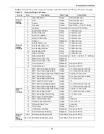
Table 17
Setpoint parameters
Button
Range
Default
Comments
Fast UV Setting (%)
-10 to -30% of Nominal
voltage rating
-20%
Set in increments of 1%.
Slow UV Setting (%)
-5 to -20%
-10%
Set in increments of 1%.
Slow UV detection delay
1-60 cycles
5 cycles
Units: Line Cycle
OV Setting (%)
+5% to +20%
+10%
Set in increments of 1%.
OV Detection Delay
1-255 cycles
3 cycles
Units: 1/4 Line Cycle
I-PK Xfer Lockout
0 – 3.0 multiplied by
the unit current rating.
2.5 Times Unit
Current Rating
I-peak xfer lockout detection point.
Units: Amps RMS. Select the HI or
LO buttons to configure your setting.
Содержание PDUTM
Страница 1: ...POWER DISTRIBUTION STS2 PDU INSTALLATION OPERATION MAINTENANCE MANUAL 250A 800A Three Phase 60 Hz ...
Страница 25: ...Installation Drawings 17 7 0 INSTALLATION DRAWINGS Figure 7 Outline drawing 250A STS2 PDU ...
Страница 26: ...Installation Drawings 18 Figure 8 Outline drawing 250A STS2 PDU with right side I Line distribution ...
Страница 27: ...Installation Drawings 19 Figure 9 Outline drawing 250A STS2 PDU with right side inline distribution ...
Страница 28: ...Installation Drawings 20 Figure 10 Outline drawing 250A STS2 PDU with left side I Line distribution ...
Страница 29: ...Installation Drawings 21 Figure 11 Outline drawing 250A STS2 PDU with left side Inline distribution ...
Страница 30: ...Installation Drawings 22 Figure 12 Outline drawing 400 600A STS2 PDU with right side inline distribution ...
Страница 32: ...Installation Drawings 24 Figure 14 Outline drawing 400 600A STS2 PDU with left side inline distribution ...
Страница 35: ...Installation Drawings 27 Figure 17 Outline drawing 800A STS2 PDU with right side inline distribution ...
Страница 37: ...Installation Drawings 29 Figure 19 Outline drawing 800A STS2 PDU with left side inline distribution ...
Страница 38: ...Installation Drawings 30 Figure 20 Outline drawing 250A STS2 PDU with key lockout switch option ...
Страница 41: ...Installation Drawings 33 Figure 23 Electrical field connections 250A STS2 PDU input output with CB8 ...
Страница 42: ...Installation Drawings 34 Figure 24 Electrical field connections 250A STS2 PDU input with CB3 ...
Страница 43: ...Installation Drawings 35 Figure 25 Electrical field connections 250A STS2 PDU input with CB3 CB3A ...
Страница 44: ...Installation Drawings 36 Figure 26 Electrical field connections 400 600A STS2 PDU input with CB3 ...
Страница 45: ...Installation Drawings 37 Figure 27 Electrical field connections 400 600A STS2 PDU input with CB3 and CB3A ...
Страница 46: ...Installation Drawings 38 Figure 28 Electrical field connections 800A STS2 PDU input with CB3 ...
Страница 47: ...Installation Drawings 39 Figure 29 Electrical field connections 800A STS2 PDU input with CB3 and CB3A ...
Страница 48: ...Installation Drawings 40 Figure 30 Electrical field connections 250A STS2 PDU output with inline panelboards ...
Страница 50: ...Installation Drawings 42 Figure 32 Electrical field connections STS2 PDU output with I Line panelboard ...
Страница 53: ...Installation Drawings 45 Figure 35 Electrical field connections 800A STS2 PDU with right side output breaker ...
Страница 54: ...Installation Drawings 46 Figure 36 Electrical field connections 8600A STS2 PDU with left side output breaker ...
Страница 55: ...Installation Drawings 47 Figure 37 Electrical field connections 800A STS2 PDU interconnect wiring ...
Страница 57: ...Installation Drawings 49 Figure 39 Electrical field connections 800A STS2 PDU interconnect wiring STS section ...
Страница 63: ...Installation Drawings 55 Figure 45 Control wiring 800A STS2 PDU left side distribution ...
Страница 64: ...Installation Drawings 56 Figure 46 Control wiring 800A STS2 PDU right side distribution ...
Страница 65: ...Installation Drawings 57 Figure 47 Control connection location 250A STS2 PDU ...
Страница 66: ...Installation Drawings 58 Figure 48 Control connection location 400 800A STS2 PDU ...
Страница 67: ...Installation Drawings 59 Figure 49 Control location drawing conduit box top entry 400 600A STS2 PDU ...
Страница 68: ...Installation Drawings 60 Figure 50 Control wiring for the programmable relay board option ...
Страница 69: ...Installation Drawings 61 Figure 51 Control wiring for the input contact isolator board option ...
Страница 70: ...Installation Drawings 62 Figure 52 Control wiring for comms board ...
Страница 71: ...Installation Drawings 63 Figure 53 Control wiring for the internal modem option ...
Страница 72: ...Installation Drawings 64 Figure 54 Control wiring for the Network Interface Card NIC option ...
Страница 73: ...Installation Drawings 65 Figure 55 Control wiring for the RS 232 Port ...
Страница 74: ...Installation Drawings 66 Figure 56 Control wiring for remote source selection option ...
Страница 75: ...Installation Drawings 67 Figure 57 Color LCD touch screen display ...
Страница 155: ......


